EPM 9650/9800 Meters
Page
EPM 9650/9800 Meters Modbus Protocol & Register Map
Customer Service and Support
Product Warranty
Limitation of Warranty
Statement of Calibration
Table of Contents
Page
Page
Page
Communication Data Formats
Page
Logs, Port Control and Updating Programmable Settings
EPM Programmable Settings Blocks
Modbus Register Map Notes
EPM Log Formats
Register Block Titles with Descriptions
Page
Xii
Appendix a Glossary
Xiv
Communication Packets
Introduction
Slave Address and Broadcast Request
Function Codes
Function Codes
Function Code Description Hex Dec
Function Code 03-Read Holding Registers
Function Code 06-Preset Single Register
Function Code 10-Preset Multiple Registers
Function Code 6 Example Master Packet Slave Packet
Data Starting Address
CRC Error Checksum Algorithm
Function Code 10 Example Master Packet Slave Packet
Exception Response Error Codes
Dead Time
Modbus Extensions
Modbus Extensions
Function Code Description
Function Code
Function Code 23H Read Holding Registers Multiple Times
Repeat Count RTU Framing Ascii Framing
Function Code 42H Encapsulated DNP for LAN/WAN
Function Code 23H Example Response
Error Code
Address
Link Status
Client IP
Request PDU
Response PDU Field Name Hex DNP Field
Response PDU
Page
Chapter EPM Modbus Register Map
Page
DNP
DNP
DNP
DNP
DNP
DNP
DNP
DNP
DNP
DNP
DNP
VAH
DNP
DNP
DNP
DNP
DNP
DNP
DNP
DNP
DNP
DNP
DNP
DNP
DNP
DNP
DNP
DNP
DNP
DNP
DNP
DNP
DNP
DNP
DNP
DNP
DNP
DNP
DNP
DNP
DNP
DNP
DNP
DNP
DNP
DNP
DNP
DNP
DNP
DNP
DNP
DNP
DNP
DNP
DNP
DNP
DNP
DNP
DNP
DNP
DNP
02771 232 Limit States, Value Comparisons 02772 16-31
VAH
DNP
DNP
DNP
DNP
DNP
DNP
DNP
DNP
DNP
DNP
DNP
DNP
DNP
DNP
DNP
DNP
DNP
DNP
DNP
DNP
DNP
DNP
DNP
DNP
DNP
Time of Use Current Month Label Block
DNP
DNP
DNP
F12 KYZ Output Accumulation Block
Analog Input Modules Data States
F19
F57
DNP
DNP
DNP
DNP
DNP
DNP
DNP
DNP
DNP
Reset Active TOU Time Stamp
DNP
DNP
DNP
DNP
DNP
DNP
DNP
DNP
DNP
DNP
DNP
DNP
DNP
DNP
DNP
DNP
DNP
DNP
DNP
DNP
DNP
DNP
Digital Output Snapshot Log Header
DNP
DNP
DNP
DNP
DNP
DNP
DNP
DNP
DNP
DNP
DNP
DNP
DNP
DNP
DNP
DNP
DNP
DNP
DNP
DNP
DNP
DNP
DNP
DNP
DNP
DNP
DNP
DNP
DNP
DNP
DNP
DNP
DNP
DNP
DNP
DNP
DNP
DNP
Custom DNP Definition Block for Analog Input Object
47369-47424 Point 1 Point
DNP
DNP
DNP
DNP
DNP
DNP
DNP
Customizable Modbus Map Settings Block
DNP LAN/WAN
DNP
DNP
DNP
DNP
DNP
DNP
DNP
Fixed Length String
Enumeration
DNP
Type F1 Null Terminated Ascii String
Type F2 Fixed Length Ascii String
Bytes
Register String
Unit
Type F3 Time Stamp
Date
Type F5 Secondary 1 Cycle RMS Voltage or Current
Type F4 Day of Week
Day of Week
Byte unsigned integer Decimal
Byte unsigned integer Hex
Secondary
Type F6 High Speed Input Delta and Current State
Byte signed integer Hex
Most significant bit Byte integer Decimal
VAR secondary
Most significant bit Compliment
Type F8 Power Factor
Quadrant Value Hex Dec
Address Value 0390H Decimal
Address Value 0C10H Decimal
Most significant bit
Type F9 Angle
Angle
Type F10 Percentage
Type F12 Energy Counter Binary / Secondary
Type F11 Energy Counter Packed BCD / Secondary
Nibbles Digit Unit VAh
Type F13 Phase Sequence
Type F14 Average Status
Byte unsigned integer
Value Hex
Bits Points Limit Passed
Type F15 Limit States
Interpretation
Type F16 Low Speed Input States
Byte
Bits
Input
Type F17 External Digital Input States
Type F19 Energy Counter Packed BCD / Primary
Type F18 External Input Accumulations
Accumulated Transitions
Type F20 Energy Counter Binary / Primary
Nibbles Digit Unit
Type F21 Year
Type F22 TOU Profile per Day
Type F23 TOU Profile Status
Day
Day Leap Year
Address35107 Value0001H Decimal1
Type F24 TOU Daily Profile Register Assignment
Value Hex Register
Nibbles
Period
Type F26 TOU Calendar DST Enable / Average Selection
Type F25 TOU Profile Monthly End Day
Decimal Month
Selection
Average
Type F27 TOU Upload Calendar Window Sequence / Status
Decimal Purpose
Type F29 TOU Upload Calendar Window Data
Type F28 TOU Upload Calendar Window ID
Address36609 Value0DH Decimal13 Meaning Window
Type F31 TOU Calendar Selection
Type F30 TOU Upload Calendar Window Checksum
Type F32 TOU Calendar Header Status / Year Status
Most significant bit Decimal
Type F33 Temperature
Celsius
Type F34 Limit and Relay Logic States
Type F35 Relay Delays
Bits Limit Logic T/F
Type F36 Desired Relay States
Type F37 Relays Pending Update
Bits Limit State NO/NC
Type F38 Shadowed Relay States
Update?
Bits Point
Type F39 Confirmed Polled Relay States
Type F40 Valid Flags for Confirmed Relay States
Type F41 Locked Relays, Relays
Locked?
Type F42 Locked Relay States
Bits Point Relay
Bit Point
Type F43 Miscellaneous Flags
Addr
Type F44 Digital Input Module Data Status
Bits Point Digital Input
Reg Bit Point
Type F45 Analog Input Modules Data Status
Bits Point Analog Input Module Status
Type F46 High Byte of Modbus Register Signed
Type F47 High Byte of Modbus Register Unsigned
Type F4 Low Byte of Modbus Register Signed
Type F49 Low Byte of Modbus Register Unsigned
Type F50 Two-Byte Signed
Type F51 Two-Byte Unsigned
Type F52 Four-Byte Signed
Type F53 Four-Byte Unsigned
Type F54 Eight-Byte Signed
Type F55 Eight-Byte Unsigned
Type F57 Accumulation in the Interval
Type F56 Flicker Countdowns
Type F58 12-bit RTU Sanity Register
Type F59 12-bit RTU Current, Voltage, W, VAR
Addr 53250
0400H
Addr 53256
Type F60 Energy Counter
Type F61 12-bit RTU Frequency
Digit Unit KWh primary
0810H
Type F62 Scaled Pulse Accumulation, Aggregation or Average
Byte Signed Integer
Most Significan Bit
Addr Hex
Type F64 Scaled Energy
Type F63 Log Index
Byte Hex
Type F65 Scaled Energy Setting
Bit Meaning
Type 66 TOU Upload Calendar Window Locked to Port
Type 67 K-Factor
Factor
Chapter Modbus Register Map Notes
Modbus Register Map Notes
Page
Downloading Logs Overview
Byte Range
Page
Steps for Downloading a Log
Downloading Time Stamps with Examples
Address Description Example Value
Page
Downloading Records with Examples
Page
Downloading Logs with Auto Index and Modbus Extensions
Auto Increment Window Index 0x099FF
Download using Auto Increment Window Sequence
Auto Increment Log Window 0x09A3F
Port Locking Overview
Sequence for Port Locking
Transmission
Reception
Port Unlocking Sequence
Updating Programmable Settings Overview
Sequence for Updating Programmable Settings
Modifications to Time of Use
Register Meaning
Clear on New Period / Freeze Period Selection
Value
Weekly Freeze Day of Week / Freeze Hour
Calibration Interface
Manual Adjustment Interface
Modbus Register Dual Port Address Name Decimal Hex
Page
Direct Adjustment Interface
As Stored LSB
Change by Multiply by
Decimal Scaled Meaning
Decimal Scaled
Change by Modified by
Chapter EPM Log Formats
Log Formats Overview
Profile Information is in the Programmable Settings Block
Historical Log 1 Format
Historical Log 1 Record Size
Historical Log 1 Data Pointers
Historical Log 2 Format
Profile Information is in the Programming Settings Block
Format Range Description
Historical Log 2 Record Size
Historical Log 2 Data Pointers
Limit Trigger Log Format
Limit Snapshot Log Format
Format Range Description
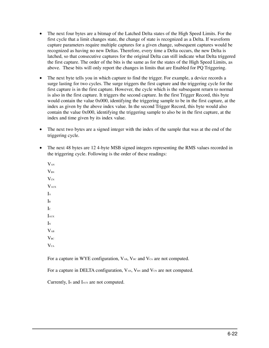
Waveform Trigger Log Format
VAN, VBN, VCN, IA, IB, IC, IAUX, VAB, VBC, VCA
High Speed Digital Input States
Above Limits
VAN VBN VCN Vaux IA IB IC Iaux
Example for EPM 9650 with regular hardware or EPM
Formula to use for EPM 9650s with 300V hardware is
Example for EPM 9650 with 300V hardware
Waveform Samples Log Format
Page
HS RMS
Page
Current Sample Examples Actual 1st Byte 2nd Byte Straight
Current Sample Examples Actual 1st Byte Straight 2nd Byte
Current Sample Examples Actual Ist Byte Straight 2nd Byte
High Speed Digital Input States
Power Quality Cbema Log Format
VAN VBN VCN Vaux IA IB IC Iaux VAB VBC VCA
11 High Speed Digital Input States
Digital Input Log Format
Byte Format Range
13 States of the Internal Digital Inputs
Digital Input Snapshot Data Pointers
Digital Input Snapshot Log Format
Format Range
Page
Digital Output Log Format
16 Relay Valid Bits
18 Relay Logic Gate Ouputs
Page
Digital Output Snapshot Log Format
Digital Output Snapshot Data Pointers
Byte Format Range Description
Flicker Log Format
System Event Log Format
Power Record
Password Record
Change Firmware
Change Programmable Settings
Change Time
Test Mode
Log Download
Feature Reset
Limit Settings Block
Communication Settings Block
Communication Settings Block Specifications
Structure for a combination is
Structure for the Direction and Combination byte is
Historical Log Settings Block
Pollable information would consist
Data Pointer 4-Byte Structure
Format Description
Waveform/CBEMA Settings Block
Waveform & PQ enable
Set Points
Sample Rate
External Digital Input Module Settings Block
High Speed Inputs Settings Block
External Digital Output Module Settings Block
External Analog Input Module Settings Block
External Analog Output Module Settings Block
External KYZ Output Module Settings Block
KYZ Output Relay Byte Energy Assignments
11 CT & PT Ratio Settings Block
Hookup and Time Settings Block
Average Settings Block
Exception Profile Block
Network Settings Block
Device Label Settings Block
Port 2 Baud Rate Values
Mode 2 Network Mode 2 byte
Server / Service Enable
Display Configuration Block
Block Window Average External Synchronization Block
Energy Direction Block
Proper Values for BWA Synch Mask Assigned Inputs
Full Scale Block
Test Mode Configuration Block
External Module Software Interface Block
External Module Port Assignment Block
Manual Control Relay Block
External Module Port Assignments
Value Assignments
Internal Input Pulse Accumulation Scale Factor Block
Internal KYZ Settings Block 46330-46372- EPM 9800 Only
26 I2t and V2t Threshold Block
Internal KYZ Channel Assignment
Internal KYZ Enable Assignment Bit
Channel Assignment
Internal Input Pulse Accumulation Unit Label Block
End of Interval Pulse Byte Value Enable
Width milliseconds
ElectroLogic Block
Format of a Relay Structure
External Analog Output Module Channel Update Block
External Analog Output Module Update Speed
Value Update
Structure for the Direction and Combination byte
Bytes to be Sent Out
Miscellaneous DNP Settings Block
Value Time 1 Minute Interval
DNP Freeze Date & Time 4 registers, 8 bytes
Registers Byte Name Range
Custom DNP Definition Block for Analog Input Object 30
Custom DNP Definition Block for Binary Counter Object 20
Class Assignments for Counter Change Event Bit
Custom DNP Definition Block for Binary Input Object 1
Bit Resets
Custom DNP Definition Block for Binary Output Object 10
Custom DNP Definition Block for Global Values
Analog Input Scaling Factors Block
Analog Input Labels Block
External Digital Input Module Labels Block
Internal Modem Card Settings Block
EPM Internal Modem Card Baud Rate Settings
Index Baud Rate INP
Bit 2 Bit Parity
Internal Modem Card Bitmap Settings
Numeric Pager ID 7 bytes Reserved for future use
Modem Feature Dial-Out Mask Event Mask
Bit Event Description
Customizable Modbus Map Settings Block
Email Mode Bitmap
Enable / Disable 1 Register
Email Client Settings Network Settings 10/100 Card
FTP Client Network Settings 10/100 Card
GE EGD Protocol Network Settings 10/100 Card
Connection Type/Option Bits
DNP LAN/WAN
Validate Connection Count 1 byte unsigned integer
DNP LAN/WAN Bitmap
Customizable Modbus Map Format Block
Energy Scale Settings
Line Number 2 bytes Point Number 1 byte
Update Settings Block
Page
Device Indentification Block
Real Time Block
On Time
Current Time
Tenth Second Block
1 Cycle Block
One Second Block
Thermal Average Block
Maximum Block
Minimum Block
Maximum Time Stamp Block
Harmonic Phase Block
Phase Angle Block
Harmonic Magnitude Block
14 THD/K-Factor Block
Digital Input Block
Primary Accumulation Block
Time of Use Period Time Stamp Block
Time of Use Frozen Block
Time of Use Prior Month Register Block
Time of Use Prior Month Total Block
Time of Use Active Register Block
Time of Use Active Total Block
Temperature
Time of Use Current Month Total Block
Time of Use Frozen Label Block
Time of Use Prior Month Label Block
Reset Time Block
Analog Input Block
Limit Combination Block
Relay Logic Block
Test Mode Block
KYZ Output Accumulation Block
Input Module Data Status Block
Flicker Status Block
Energy and Pulses in the Interval Block
Flicker Countdown Block
Cumulative Demand Block
Time of Use Active Cumulative Demand Block
Total Average Power Factor Block
TOU Active Continuous Cumulative Demand Block
TOU Current Month Continuous Cumulative Demand Block
Log Index Block
Reset Active Time of Use Time Stamp
Enhanced Factory Settings Block
Enhanced Programmable Settings Block
Negative Maximum Pulse Aggregation Average Block
Time of Use Upload Calendar Block
Time of Use Calendar Block
Historical Log 1 Snapshot Header
Historical Log 2 Snapshot Header
Limit Trigger Log Header
Limit Snapshot Log Header
Digital Input Log Header
Flicker Log Header
Waveform Trigger Log Header
System Event Log Header
Valid Bitmap Undefined
Reset Log Header
Waveform Samples Log Header
PQ Cbema Log Header
External Device Information Block Header
Device History Block Header
Direct Memory Access Header
Window Index Block
Page
Window Mode Block
Page
Window Block
Page
Auto Increment Window Block
„ Auto Increment Configuration 1 Register, 2 bytes
„ Auto Increment Window Index 1 register, 2 bytes
„ Auto Increment Log Window 64 registers, 128 bytes
Alarm Block
Byte Format Range Description
Last Alarm Snapshot
Format Description
Port Control Block
Port Control Lock States Register High Byte Low Byte
Receive and Transmit Buffers Port
Transmit
97 12-bit RTU Block
Energy Preset Block
Current, Voltage, W, VAR 1 register, 2 bytes
Action Block Resetting EPM Registers
Voltage Calibration Inputs Model
Current Calibration Inputs Model
Factory Calibration Block
Ctpt Compensation Calibration Block
Calibration Modification Block
Relay Locking Action Selection Values ValueDescription
Operational Communication Settings Block
Diagnostic Block
Device Identification Block 2
Xilinx Version / 320 Xilinx Version
DSP Diagnostic Block
Password Block
Sealing Switch State
Firmware Variation Strings
New Password a New Password B
Dynamic Configuration Block
Hardware Option Settings
Nvram Configuration Values
Hardware Options Block
EPM Forms Code
Banked Executable Option Settings Modbus Register 9650 9800
CT’s PTs
Amp 65364 High
300 V 65364 Low
Flash Control Block
Page
Flash Locked Port
GE Communicator EXT Flash Code Hex Line
Enhanced Serial Number
Serial Number
Page
Glossary
Eeprom
LCD
Nvram
Glossary-5
THD