RPC SERIES OWNER’S MANUAL
RPC SERIES QUICK START
________________________________________________________________________________
Using the RJ04X007
Using the
OPERATION
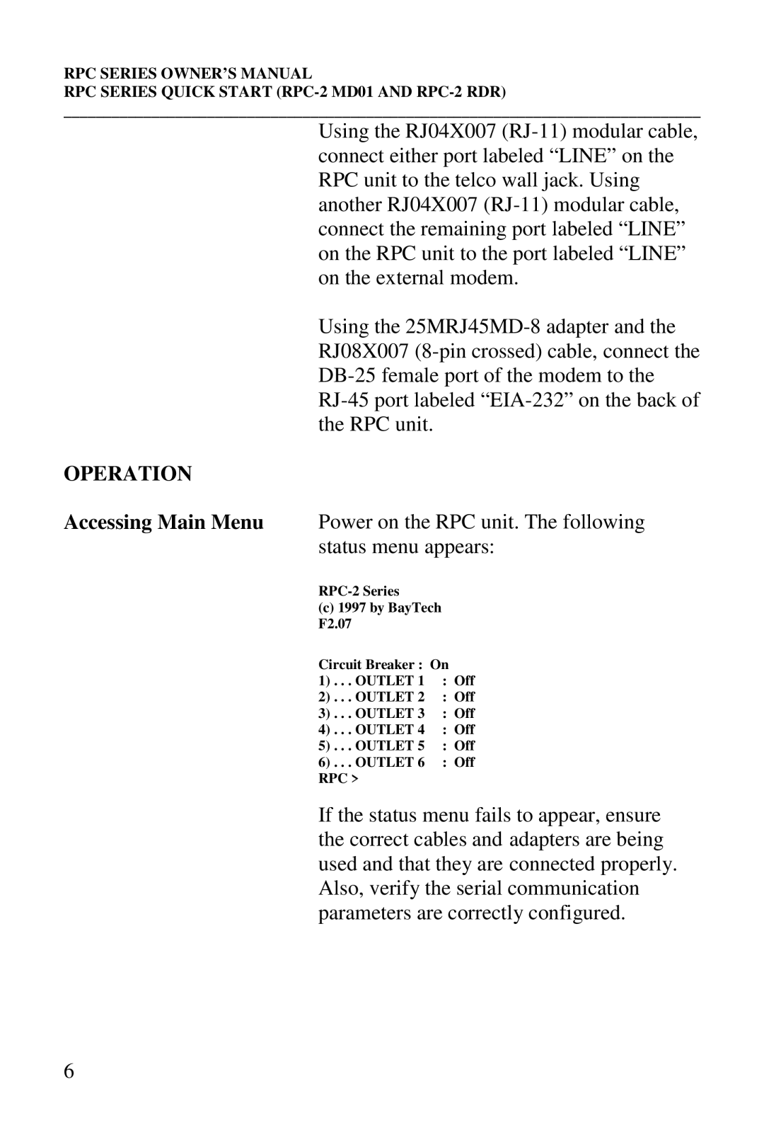
Accessing Main Menu Power on the RPC unit. The following status menu appears:
(c)1997 by BayTech
F2.07
Circuit Breaker : On
1) . . . OUTLET 1 | : Off |
2) . . . OUTLET 2 | : Off |
3) . . . OUTLET 3 | : Off |
4) . . . OUTLET 4 | : Off |
5) . . . OUTLET 5 | : Off |
6) . . . OUTLET 6 | : Off |
RPC > |
|
If the status menu fails to appear, ensure the correct cables and adapters are being used and that they are connected properly. Also, verify the serial communication parameters are correctly configured.
6