BayTech Manual Publication #U140E125-03 July
RPC-2 RDR RPC-3 RPC-3A RPC-5
Page
Page
Page
Page
ADD User Delete User Change Password
Vii
230 VAC, 50/60 Hz, 10 Amp
Introduction to the Remote Power Control Switch RPC
115 VAC, 50/60 Hz, 15 Amp
Operation
RPC Series Quick Start
RPC-2 and RPC-2A Quick Start
Or for the RPC-2A
RPC Series Quick Start RPC-2 and RPC-2A
RPC-2 RDR
RPC-2 MD01 and RPC-2 RDR Quick Start
Operation
Change Password
Configuration
Network port
Remote access using
RPC-3, RPC-3A and RPC-5 Quick Start
Manage Users
Deletion of the admin user is prohibited
Outlet Control
List
Change Password Default password is cr disabled
8. Default is no outlets selected
Change Outlet
Logout
Reset Unit
Unit Status
Unpacking
Installation
Preparing the Installation Site
Power
Circuit Breaker
Power ON/OFF State
Power UP Sequence
RJ-45 Cables and Adapters
Cabling
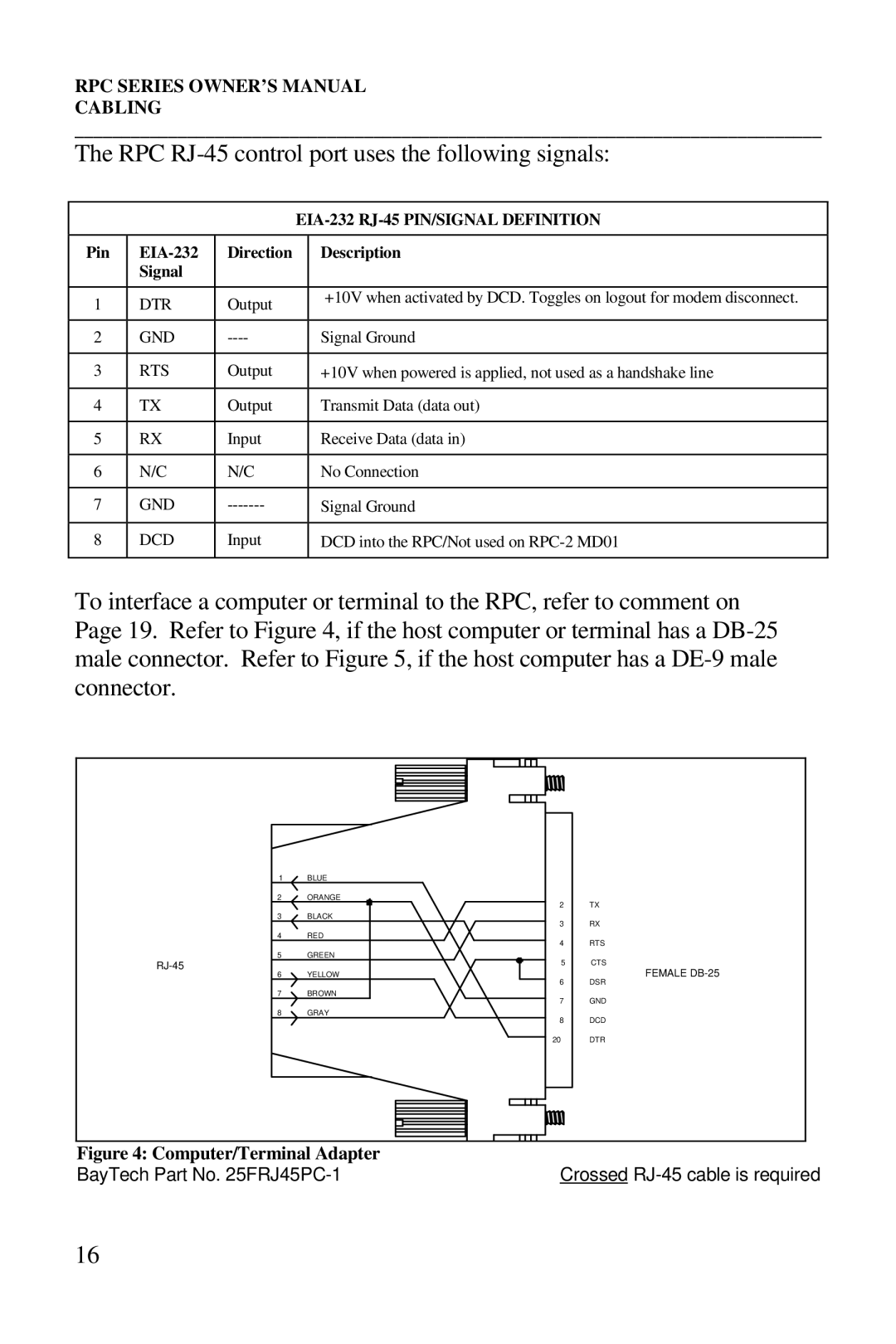
RPC RJ-45 control port uses the following signals
Computer/Terminal Adapter
Crossed 8-pin Modular Cable
RPC-2 and RPC-2A
Detailed Operation Configuration
RPC’s main menu allows the user to
Controlling Receptacles
Detailed Operation and Configuration
Select #1, Change Password, and press
Enter New Password
Key at the Enter Request prompt
To return to the RPC prompt, press any
Change the current status. Default is
From the configuration menu, select #3
Enable/Disable Confirmation
Switch, the RPC responds with the option to
Serial Connection
Local Access
Using the EIA-232
RPC-2 MD01 and RPC-2 RDR
Remote Access Using Modem Connections
RPC’s main menu allows you to
Responding Y for yes turns On Outlet
If prompted, enter password. The following main menu appears
Outlet
RPC Config
RPC
Outlet Enter Request
RPC-3 and RPC-3A and RPC-5
Port Connection
Using EIA-232
Remote Access
Using Network
Operation
Detailed Operation and Configuration
And/or password has been entered, the main
If this is not an initial setup and username
And/or password have been enabled, you
Password. When a successful username
To On in the status menu
Responding Y for yes turns On Outlet
Observe the status of Outlet 3 has changed
With the option to delete users
If this is not an initial setup and optional
Outlet users have been added, they too will
Show in the User Management Menu, along
Delete user
Add User
Default password is cr
Enter new password = 8 characters
To change outlet access, enter numbers of outlets. If
Network port. From the RPC Main Menu
Configuration can be performed by
Admin user only via the serial port or
Select #3, Configuration. The following
Default Subnet Mask is 0.0.0.0. If you fail
Access
Default Unit ID is RPC-3
Outlet Operation Configuration Menu
Disable Outlet Status Display? Y/N
Outlet 1, Outlet 2, Outlet 3 . . . Outlet
Unique set-up.Default outlet names are
Name Outlets
To return to the configuration menu, press any key
Interface, logged user status, and outlet
Status. In the event of problems with
Unit status provides vital information about
RPC unit system status, network
System Status
Enter the number of the session to terminate RPC responds
Changes
Reset the unit to load new configuration
Status
Technical Support
Outlet
Equipment Setup
RPC Series Unit Model RPC Series Unit Serial Number
Outlet OUTLET3
Instructions for Repackaging and Shipping
Call BayTech to get a Return Authorization Number
REPACKAGING, Shipping and Returning to the Factory
FCC Requirements for the RPC-2 MD01 and RDR
FCC Radio Frequency Interface Statement
FCC Radio Frequency Interface Statement
Appendix a
Specifications
Specifications
Robotic Modems
Modem Command Summary
Appendix B
Rockwell Chip SET Modems
Save modem’s configuration in non-volatile memory
Indication Interpretation
Diagnostic LED Indications
Appendix C
Appendix D
RPC Troubleshooting Guide
Problem Symptom Cause Solution
Appendix D RPC Troubleshooting Guide Cont’
Appendix D RPC Troubleshooting Guide Cont’
RPC-2
Appendix E- Drawings
RPC-2A
RPC-2 MD01
RPC-2 RDR
RPC-3
RPC-3A
RPC3/3A/5 Ethernet Board
RPC-5
Index
Shipping