Serial Ports
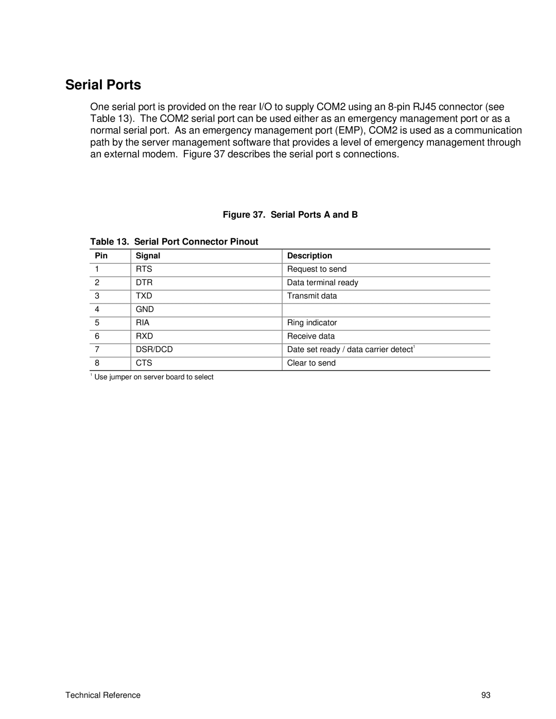
One serial port is provided on the rear I/O to supply COM2 using an
|
| Figure 37. Serial Ports A and B |
|
Table 13. Serial Port Connector Pinout |
|
| |
|
|
|
|
Pin | Signal | Description |
|
|
|
|
|
1 | RTS | Request to send |
|
|
|
|
|
2 | DTR | Data terminal ready |
|
|
|
|
|
3 | TXD | Transmit data |
|
|
|
|
|
4 | GND |
|
|
|
|
|
|
5 | RIA | Ring indicator |
|
|
|
|
|
6 | RXD | Receive data |
|
|
|
|
|
7 | DSR/DCD | Date set ready / data carrier detect | 1 |
| |||
|
|
|
|
8 | CTS | Clear to send |
|
|
|
|
|
1 Use jumper on server board to select |
|
| |
Technical Reference | 93 |
