Configuration Jumpers
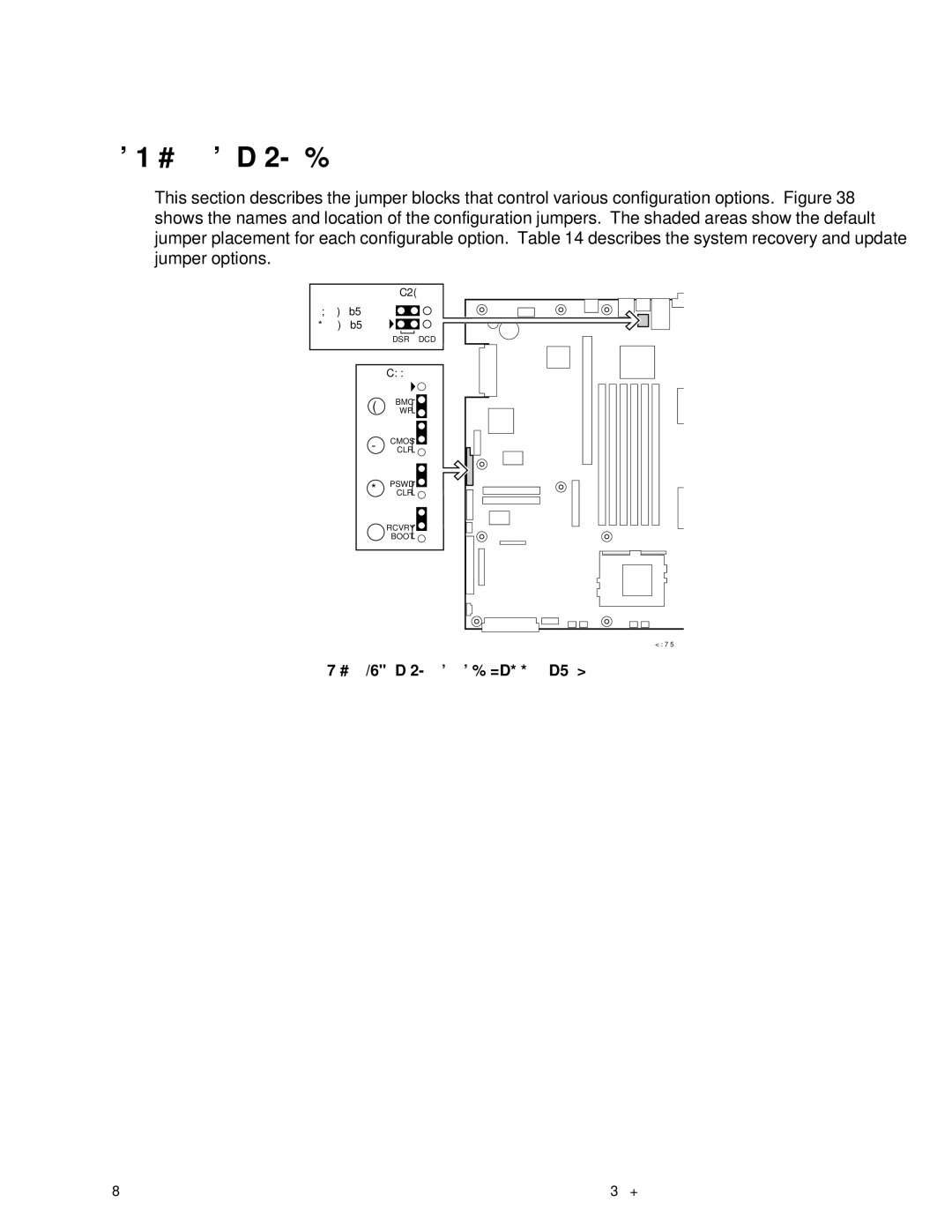
This section describes the jumper blocks that control various configuration options. Figure 38 shows the names and location of the configuration jumpers. The shaded areas show the default jumper placement for each configurable option. Table 14 describes the system recovery and update jumper options.
J6A2
DSR to Pin #7
DCD to Pin #7
DSR DCD
J1E1
A
B
BMC ![]()
![]() WP
WP ![]()
![]()
CMOS ![]()
![]() CLR
CLR ![]()
![]()
PSWD ![]()
![]()
C CLR ![]()
![]()
RCVRY ![]()
![]()
D BOOT ![]()
![]()
OM12837
Figure 38. Jumper Locations (J1E1 and J6A2)
94 | xSeries 343 Hardware Maintenance Manual |
