Chassis Feature Location
Front Panel
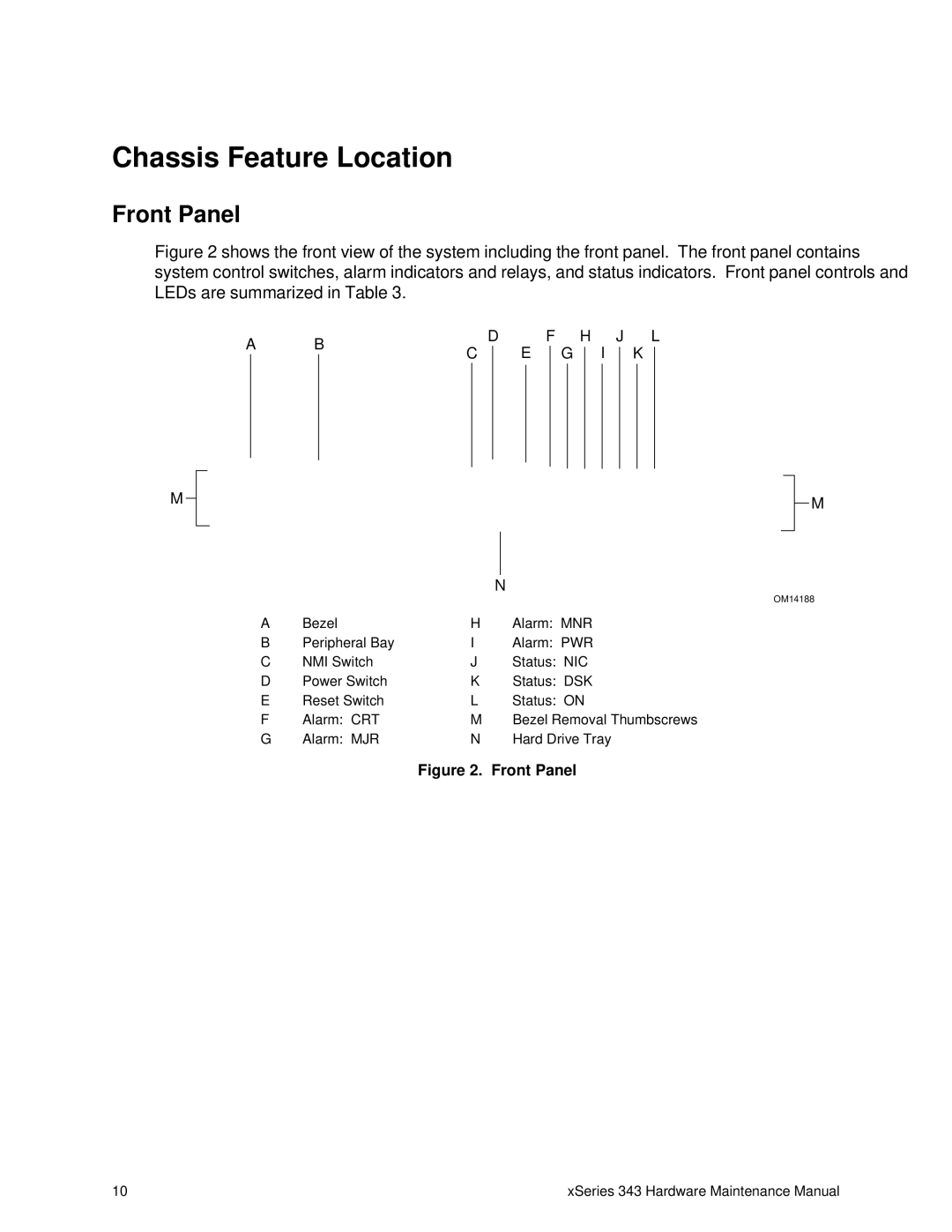
Figure 2 shows the front view of the system including the front panel. The front panel contains system control switches, alarm indicators and relays, and status indicators. Front panel controls and LEDs are summarized in Table 3.
A | B |
| D | |||
C | ||||||
|
|
|
| |||
|
|
|
|
|
| |
|
|
|
|
|
| |
F
E
| H | J |
|
| L | |||||
G |
|
| I |
|
| K |
|
| ||
|
|
| ||||||||
|
|
|
|
|
|
|
|
|
|
|
|
|
|
|
|
|
|
|
|
|
|
M
M
N
|
|
|
|
|
| OM14188 |
A | Bezel |
| H | Alarm: | MNR | |
B | Peripheral Bay | I | Alarm: | PWR | ||
C | NMI Switch | J | Status: | NIC | ||
D | Power Switch | K | Status: | DSK | ||
E | Reset Switch | L | Status: | ON | ||
F | Alarm: | CRT | M | Bezel Removal Thumbscrews | ||
G | Alarm: | MJR | N | Hard Drive Tray | ||
Figure 2. Front Panel
10 | xSeries 343 Hardware Maintenance Manual |