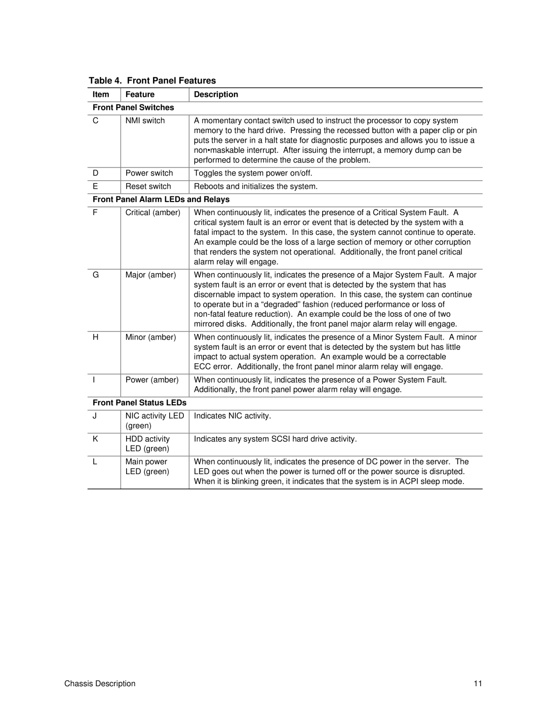
Table 4. Front Panel Features
Item | Feature | Description |
| |
|
|
|
|
|
Front Panel Switches |
|
|
| |
|
|
|
| |
C | NMI switch | A momentary contact switch used to instruct the processor to copy system | ||
|
|
| memory to the hard drive. Pressing the recessed button with a paper clip or pin | |
|
|
| puts the server in a halt state for diagnostic purposes and allows you to issue a | |
|
|
| non•maskable interrupt. After issuing the interrupt, a memory dump can be | |
|
|
| performed to determine the cause of the problem. |
|
|
|
|
|
|
D | Power switch | Toggles the system power on/off. |
| |
|
|
|
|
|
E | Reset switch | Reboots and initializes the system. |
| |
|
|
|
| |
Front Panel Alarm LEDs and Relays |
| |||
|
|
|
| |
F | Critical (amber) | When | continuously lit, indicates the presence of a Critical System Fault. A | |
|
|
| critical system fault is an error or event that is detected by the system with a | |
|
|
| fatal impact to the system. In this case, the system cannot continue to operate. | |
|
|
| An example could be the loss of a large section of memory or other corruption | |
|
|
| that renders the system not operational. Additionally, the front panel critical | |
|
|
| alarm relay will engage. |
|
|
|
|
|
|
G | Major (amber) | When | continuously lit, indicates the presence of a Major System Fault. | A major |
|
|
| system fault is an error or event that is detected by the system that has | |
|
|
| discernable impact to system operation. In this case, the system can continue | |
|
|
| to operate but in a “degraded” fashion (reduced performance or loss of | |
|
|
| ||
|
|
| mirrored disks. Additionally, the front panel major alarm relay will engage. | |
|
|
|
|
|
H | Minor (amber) | When | continuously lit, indicates the presence of a Minor System Fault. | A minor |
|
|
| system fault is an error or event that is detected by the system but has little | |
|
|
| impact to actual system operation. An example would be a correctable | |
|
|
| ECC error. Additionally, the front panel minor alarm relay will engage. | |
|
|
|
|
|
I | Power (amber) | When | continuously lit, indicates the presence of a Power System Fault. |
|
|
|
| Additionally, the front panel power alarm relay will engage. |
|
|
|
|
|
|
Front Panel Status LEDs |
|
|
| |
|
|
|
|
|
J | NIC activity LED |
| Indicates NIC activity. |
|
| (green) |
|
|
|
|
|
|
|
|
K | HDD activity |
| Indicates any system SCSI hard drive activity. |
|
| LED (green) |
|
|
|
|
|
|
| |
L | Main power |
| When continuously lit, indicates the presence of DC power in the server. The | |
| LED (green) |
| LED goes out when the power is turned off or the power source is disrupted. | |
|
|
| When it is blinking green, it indicates that the system is in ACPI sleep mode. | |
|
|
|
|
|
Chassis Description | 11 |
