Intel SBFCM, SBCEFCSW manual Switch module fault LED flash pattern, Switch module OK LED

Models: SBCEFCSW SBFCM

1 170
Download 170 pages 11.82 Kb
Page 130
Image 130
Configuration file system error LED flash pattern

Configuration file system error LED flash pattern

A configuration file system error flash pattern is four flashes per second followed by a 2-second pause, as shown in the following illustration. The four-flash error pattern indicates that a configuration file system error has occurred.

Switch module fault LED flash pattern

The amber Switch Fault LED is lit to indicate one or more of the following conditions:

POST failure

Over temperature condition

Port operational test failure. See “Port fault LED flash patterns” on page 117 for information about port operational tests.

If the Switch Fault LED is lit for reasons other than a port operational test failure, take the Fibre Channel switch module offline and contact your Intel technical support representative.

Switch module OK LED

The green OK LED is lit to indicate that the switch module has completed POST diagnostics without errors. If this LED is not lit when you turn on the Blade Server Chassis SBCE or turns off during operation, remove the switch module and inspect the connector for damage.

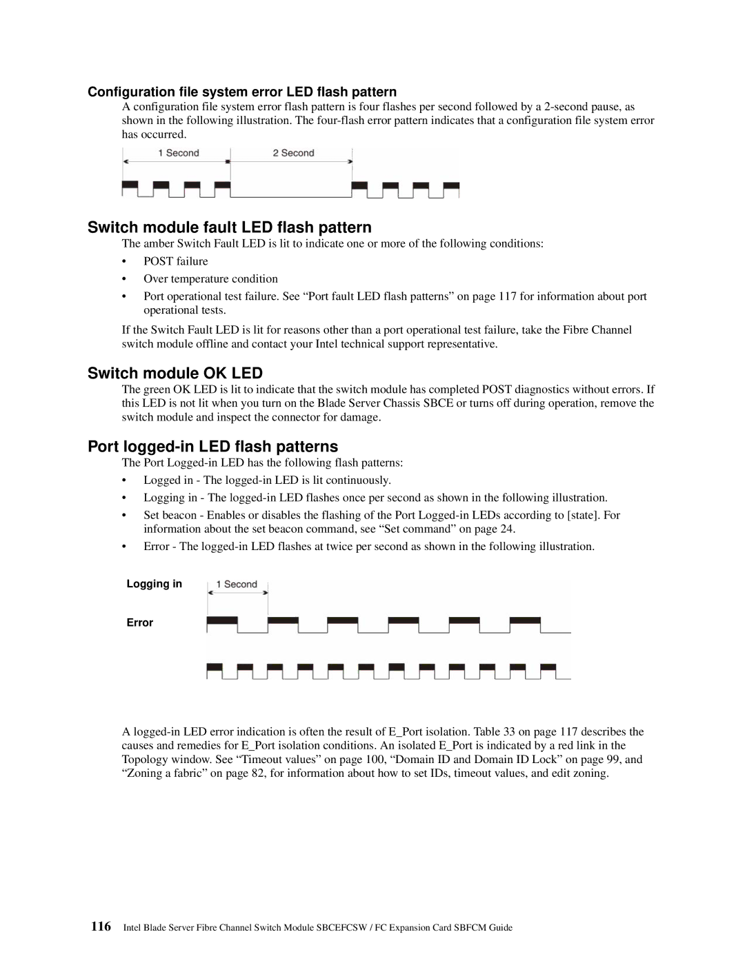
Port logged-in LED flash patterns

The Port Logged-in LED has the following flash patterns:

Logged in - The logged-in LED is lit continuously.

Logging in - The logged-in LED flashes once per second as shown in the following illustration.

Set beacon - Enables or disables the flashing of the Port Logged-in LEDs according to [state]. For information about the set beacon command, see “Set command” on page 24.

Error - The logged-in LED flashes at twice per second as shown in the following illustration.

Logging in

Error

A logged-in LED error indication is often the result of E_Port isolation. Table 33 on page 117 describes the causes and remedies for E_Port isolation conditions. An isolated E_Port is indicated by a red link in the Topology window. See “Timeout values” on page 100, “Domain ID and Domain ID Lock” on page 99, and “Zoning a fabric” on page 82, for information about how to set IDs, timeout values, and edit zoning.

116Intel Blade Server Fibre Channel Switch Module SBCEFCSW / FC Expansion Card SBFCM Guide

Page 130
Image 130
Intel SBFCM, SBCEFCSW manual Switch module fault LED flash pattern, Switch module OK LED, Port logged-inLED flash patterns