Return to Section TOC
Return to Section TOC
Return to Section TOC
Return to Master TOC
Return to Master TOC
Return to Master TOC
|
| TROUBLESHOOTING & REPAIR |
STT CURRENT TRANSDUCER TEST (CONTINUED)
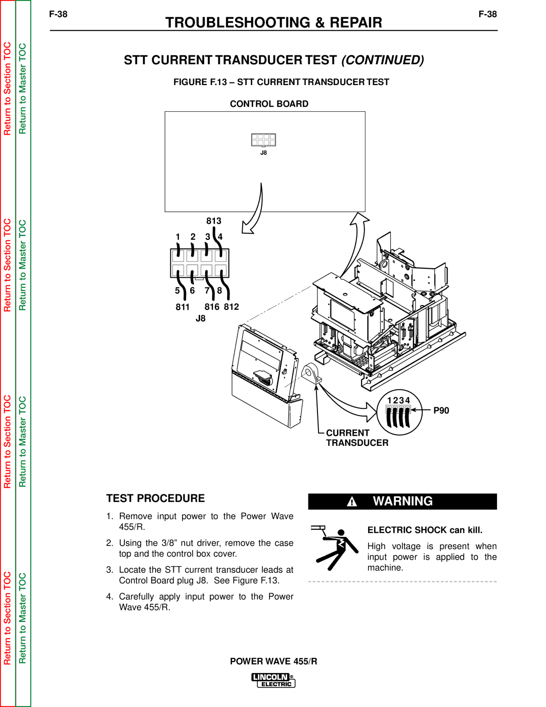
FIGURE F.13 – STT CURRENT TRANSDUCER TEST
CONTROL BOARD
J8
813
1 2 3 4
5 6 7 8
811 816 812
J8
1 2 3 4
![]()
![]()
![]()
![]()
![]()
![]()
![]() P90
P90
CURRENT
TRANSDUCER
Return to Section TOC
Return to Master TOC
TEST PROCEDURE
1.Remove input power to the Power Wave 455/R.
2.Using the 3/8” nut driver, remove the case top and the control box cover.
3.Locate the STT current transducer leads at Control Board plug J8. See Figure F.13.
4.Carefully apply input power to the Power Wave 455/R.
WARNING
ELECTRIC SHOCK can kill.
High voltage is present when input power is applied to the machine.