Return to Section TOC
Return to Master TOC
|
| TROUBLESHOOTING & REPAIR |
AUXILIARY TRANSFORMER NO. 1 REMOVAL AND
REPLACEMENT PROCEDURE (CONTINUED)
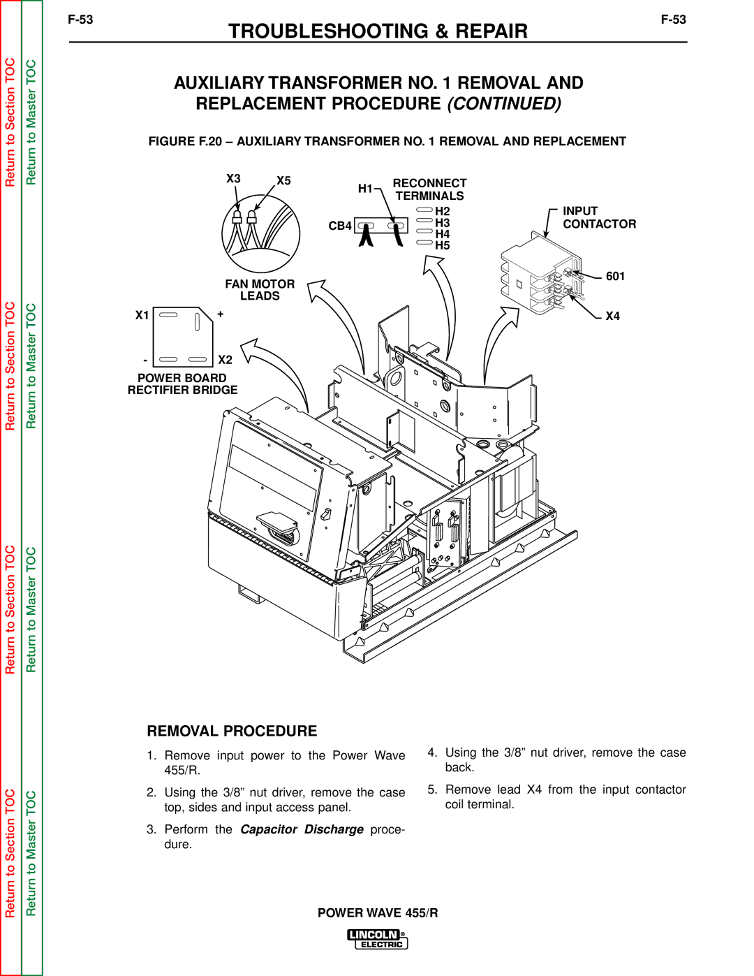
FIGURE F.20 – AUXILIARY TRANSFORMER NO. 1 REMOVAL AND REPLACEMENT
Return to Section TOC
Return to Section TOC
Return to Master TOC
Return to Master TOC
X3 | X5 | H1 | RECONNECT |
|
| TERMINALS | |
|
|
|
H2
CB4 ![]() H3
H3
H4
H5
FAN MOTOR
LEADS
X1 | + |
- ![]()
![]() X2
X2
POWER BOARD
RECTIFIER BRIDGE
INPUT CONTACTOR
![]() 601
601
X4 |
Return to Section TOC
Return to Master TOC
REMOVAL PROCEDURE
1.Remove input power to the Power Wave 455/R.
2.Using the 3/8” nut driver, remove the case top, sides and input access panel.
3.Perform the Capacitor Discharge proce- dure.
4.Using the 3/8” nut driver, remove the case back.
5.Remove lead X4 from the input contactor coil terminal.