INSTALLATION
Return to Section TOC
Return to Section TOC
Return to Master TOC
Return to Master TOC
VOLTAGE SENSING
The best arc performance occurs when the Power Wave has accurate data about the arc conditions. Depending upon the process, inductance within the electrode and work lead cables can influence the volt- age apparent at the terminals of the welder. Voltage sense leads improve the accuracy of the arc conditions and can have a dramatic effect on performance.
CAUTION
If the voltage sensing is enabled but the sense leads are missing or improperly connected, extremely high welding outputs may occur.
Do not tightly bundle the work sense lead to the work lead.
The sense leads connect to the Power Wave at the
Enable the voltage sense leads as follows:
TABLE A.2
Process | Electrode Voltage | Work Voltage |
| Sensing 67 lead * | Sensing 21 lead |
|
|
|
GMAW | 67 lead required | 21 lead optional |
67 lead required | 21 lead optional | |
FCAW | 67 lead required | 21 lead optional |
STT | 67 lead required | 21 lead required |
GTAW | Voltage sense at | Voltage sense at |
| terminals | terminals |
SAW | 67 lead required | 21 lead optional |
|
|
|
*The electrode voltage 67 sense lead is integral to the con- trol cable to the wire feeder.
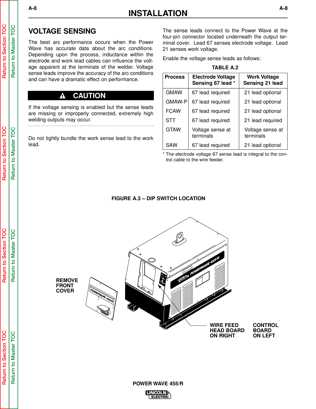
FIGURE A.3 – DIP SWITCH LOCATION
Return to Section TOC
Return to Section TOC
Return to Master TOC
Return to Master TOC
455/R WAVE POWER
|
| I | |
REMOVE |
|
| O |
|
| N | |
| O | OF | |
FRONT |
|
| |
|
| F | |
POWER |
|
| |
COVER |
|
| |
WAVE |
|
| |
| 455/R |
| |
|
|
| |
WIRE FEED | CONTROL |
HEAD BOARD | BOARD |
ON RIGHT | ON LEFT |
POWER WAVE 455/R