Return to Section TOC
Return to Section TOC
Return to Section TOC
Return to Master TOC
Return to Master TOC
Return to Master TOC
|
| TROUBLESHOOTING & REPAIR |
INPUT RECTIFIER TEST (CONTINUED)
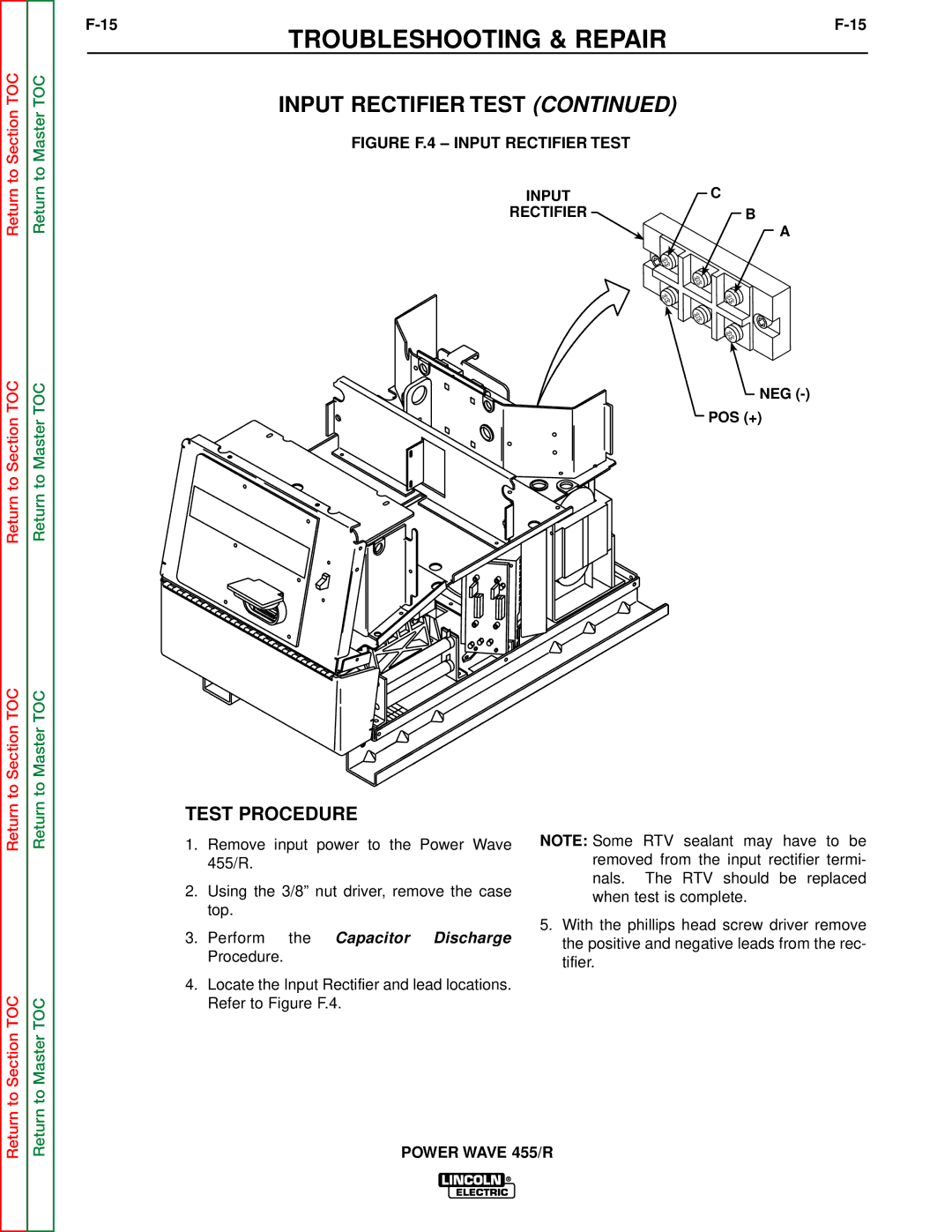
FIGURE F.4 – INPUT RECTIFIER TEST
INPUT | C |
RECTIFIER | B |
| A |
NEG
POS (+)
TEST PROCEDURE
Return to Section TOC
Return to Master TOC
1.Remove input power to the Power Wave 455/R.
2.Using the 3/8” nut driver, remove the case top.
3.Perform the Capacitor Discharge Procedure.
4.Locate the Input Rectifier and lead locations. Refer to Figure F.4.
NOTE: Some RTV sealant may have to be removed from the input rectifier termi- nals. The RTV should be replaced when test is complete.
5.With the phillips head screw driver remove the positive and negative leads from the rec- tifier.