Section TOC
Master TOC
|
|
| ||
| INSTALLATION |
| ||
INPUT VOLTAGE CHANGE OVER |
| WELDING WITH MULTIPLE POWER |
| |
(FOR MULTIPLE INPUT VOLTAGE |
| WAVES |
| |
MACHINES ONLY) |
|
|
|
|
|
| CAUTION |
| |
|
|
|
| |
Welders are shipped connected for the highest input voltage listed on the rating plate. To move this con- nection to a different input voltage, see the diagram located on the inside of the input access door. (Figure A.1.) If the main reconnect switch or link position is placed in the wrong position, the welder will not pro- duce output power.
If the Auxiliary (A) lead is placed in the wrong position, there are two possible results. If the lead is placed in a position higher than the applied line voltage, the welder may not come on at all. If the auxiliary (A) lead is placed in a position lower than the applied line volt- age, the welder will not come on, and the two circuit breakers in the reconnect area will open. If this occurs, turn off the input voltage, properly connect the (A) lead, reset the breakers, and try again.
Special care must be taken when more than one Power Wave is welding simultaneously on a single part. Arc blow and arc interference may occur or be magnified.
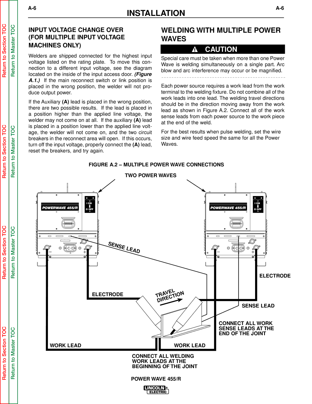
Each power source requires a work lead from the work terminal to the welding fixture. Do not combine all of the work leads into one lead. The welding travel directions should be in the direction moving away from the work lead as shown in Figure A.2. Connect all of the work sense leads from each power source to the work piece at the end of the weld.
For the best results when pulse welding, set the wire size and wire feed speed the same for all the Power Waves.
Return
Return to Section TOC
Return
Return to Master TOC
FIGURE A.2 – MULTIPLE POWER WAVE CONNECTIONS
TWO POWER WAVES
|
|
|
|
|
|
|
|
|
|
|
|
|
| I ON |
|
|
|
| I ON | ||||
|
|
|
|
|
| ||||||
POWERWAVE 455/R |
|
|
| POWERWAVE 455/R |
| ||||||
|
|
|
|
|
|
|
|
|
| ||
| O OFF |
|
|
| O OFF | ||||||
|
|
|
|
|
|
|
|
|
|
|
|
SENSE | LEAD |
|
ELECTRODE
Return to Section TOC
Return to Master TOC
ELECTRODE | TRAVEL | |
DIRECTION | ||
|
WORK LEAD | WORK LEAD |
CONNECT ALL WELDING
WORK LEADS AT THE
BEGINNING OF THE JOINT
SENSE LEAD
CONNECT ALL WORK SENSE LEADS AT THE END OF THE JOINT
POWER WAVE 455/R