Return to Section TOC
Return to Section TOC
to Section TOC
Return to Master TOC
Return to Master TOC
to Master TOC
|
|
| INSTALLATION |
|
|
| |||
|
|
|
|
|
|
|
| ||
|
|
|
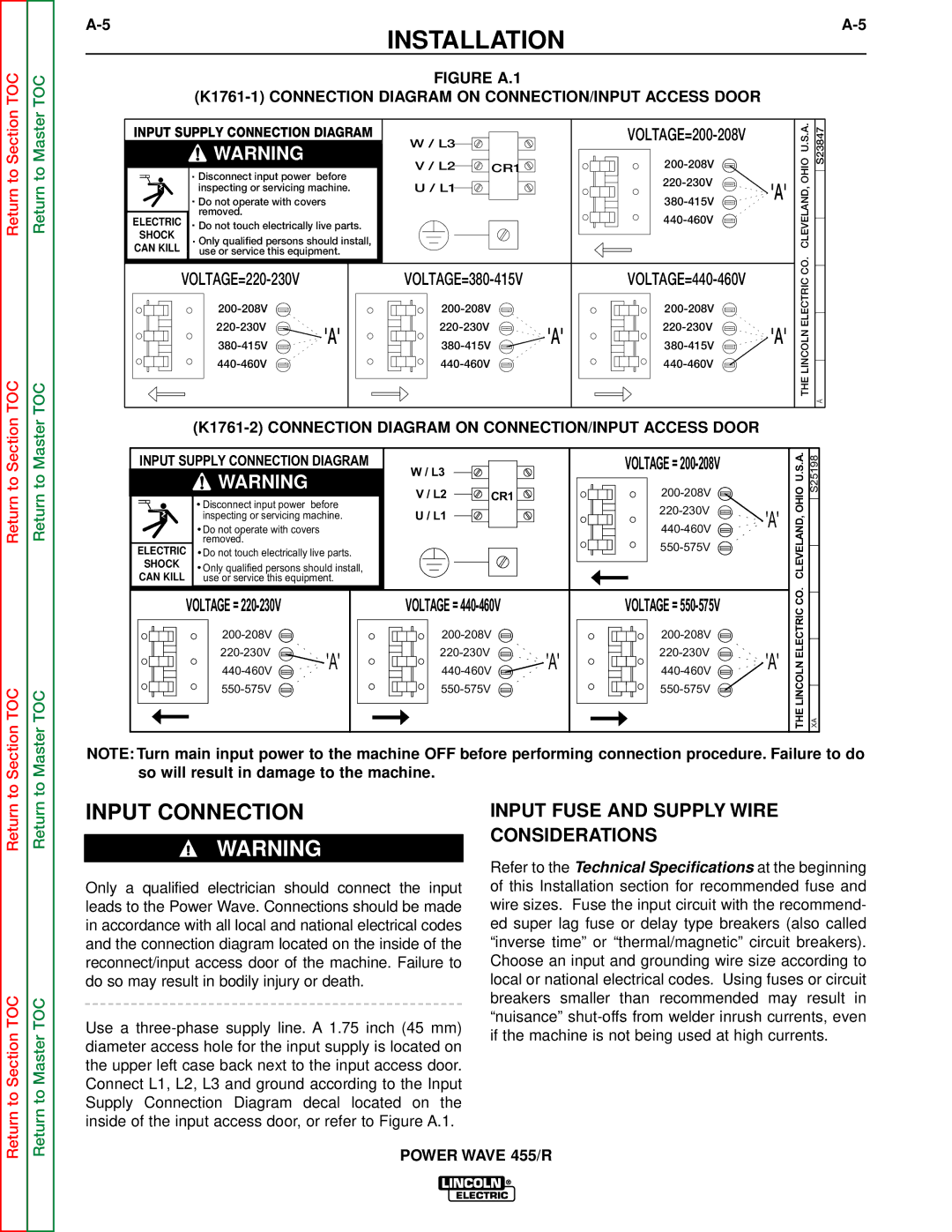
| FIGURE A.1 |
|
|
|
| |
|
|
| OHIOU.S.A. | S23847 | |||||
| . | Disconnect input power before |
|
|
|
| |||
INPUT SUPPLY CONNECTION DIAGRAM | W / L3 |
|
|
|
| ||||
|
| WARNING |
|
|
|
|
|
| |
|
|
| V / L2 | CR1 |
|
|
| ||
|
|
|
|
|
|
| |||
|
| inspecting or servicing machine. | U / L1 |
| 'A' | CLEVELAND, |
| ||
| . |
|
|
| |||||
| Only qualified persons should install, |
|
|
| |||||
| . | Do not operate with covers |
|
|
|
| |||
|
| removed. |
|
|
|
|
|
| |
ELECTRIC . Do not touch electrically live parts. |
|
|
|
|
| ||||
SHOCK |
|
|
|
|
|
|
|
|
|
CAN KILL |
| use or service this equipment. |
|
|
|
| CO. |
| |
|
|
|
| ||||||
|
|
| ELECTRIC |
| |||||
|
|
|
|
|
| ||||
|
|
|
|
|
|
| |||
|
| 'A' | 'A' | 'A' | LINCOLNTHE |
| |||
|
|
| |||||||
|
|
|
|
|
| ||||
|
|
|
|
|
|
| |||
|
|
|
|
|
|
|
|
| A |
INPUT SUPPLY CONNECTION DIAGRAM | W / L3 |
|
| VOLTAGE = |
| U.S.A.OHIO | S25198 | |
WARNING |
|
|
|
|
|
| ||
|
|
|
|
|
|
| ||
WARNING | V / L2 | CR1 |
|
|
|
| ||
|
|
|
|
|
| |||
|
| U / L1 |
|
| 'A' | CLEVELAND, |
| |
|
|
|
|
|
| |||
|
|
|
|
|
| |||
|
|
|
|
|
|
| ||
ELECTRIC |
|
|
|
|
|
|
| |
|
|
|
|
|
|
|
| |
SHOCK |
|
|
|
|
|
|
|
|
CAN KILL |
|
|
|
|
|
|
|
|
VOLTAGE = |
| VOLTAGE = |
| VOLTAGE = |
| CO. |
| |
|
|
| ELECTRIC |
| ||||
|
|
|
|
| ||||
|
|
|
|
| ||||
'A' | 'A' | 'A' | LINCOLNTHE |
| ||||
|
|
|
| XA | ||||
|
|
|
|
|
| |||
NOTE: Turn main input power to the machine OFF before performing connection procedure. Failure to do so will result in damage to the machine.
Return
Return to Section TOC
Return
Return to Master TOC
INPUT CONNECTION
WARNING
Only a qualified electrician should connect the input leads to the Power Wave. Connections should be made in accordance with all local and national electrical codes and the connection diagram located on the inside of the reconnect/input access door of the machine. Failure to do so may result in bodily injury or death.
Use a
INPUT FUSE AND SUPPLY WIRE
CONSIDERATIONS
Refer to the Technical Specifications at the beginning of this Installation section for recommended fuse and wire sizes. Fuse the input circuit with the recommend- ed super lag fuse or delay type breakers (also called “inverse time” or “thermal/magnetic” circuit breakers). Choose an input and grounding wire size according to local or national electrical codes. Using fuses or circuit breakers smaller than recommended may result in “nuisance”
POWER WAVE 455/R