Return to Section TOC
Section TOC
Return to Master TOC
Master TOC
THEORY OF OPERATION
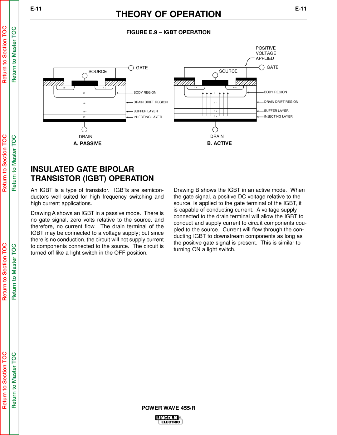
FIGURE E.9 – IGBT OPERATION
POSITIVE
VOLTAGE
APPLIED
| GATE |
| GATE |
SOURCE | SOURCE | ||
n + | n + | n + | n + |
p | BODY REGION | p | BODY REGION |
n - | DRAIN DRIFT REGION | n - | DRAIN DRIFT REGION |
n + | BUFFER LAYER | n + | BUFFER LAYER |
p + | INJECTING LAYER | p + | INJECTING LAYER |
DRAIN |
| DRAIN |
|
A. PASSIVE |
| B. ACTIVE |
|
Return to
Return to Section TOC
Return to
Return to Master TOC
INSULATED GATE BIPOLAR TRANSISTOR (IGBT) OPERATION
An IGBT is a type of transistor. IGBTs are semicon- ductors well suited for high frequency switching and high current applications.
Drawing A shows an IGBT in a passive mode. There is no gate signal, zero volts relative to the source, and therefore, no current flow. The drain terminal of the IGBT may be connected to a voltage supply; but since there is no conduction, the circuit will not supply current to components connected to the source. The circuit is turned off like a light switch in the OFF position.
Drawing B shows the IGBT in an active mode. When the gate signal, a positive DC voltage relative to the source, is applied to the gate terminal of the IGBT, it is capable of conducting current. A voltage supply connected to the drain terminal will allow the IGBT to conduct and supply current to circuit components cou- pled to the source. Current will flow through the con- ducting IGBT to downstream components as long as the positive gate signal is present. This is similar to turning ON a light switch.
Return to Section TOC
Return to Master TOC