Return to Section TOC
Return to Section TOC
Return to Section TOC
Return to Master TOC
Return to Master TOC
Return to Master TOC
|
| TROUBLESHOOTING & REPAIR |
CONTROL, FEED HEAD, OR VOLTAGE SENSE PC BOARD
REMOVAL AND REPLACEMENT (CONTINUED)
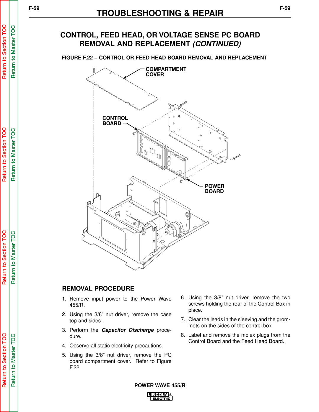
FIGURE F.22 – CONTROL OR FEED HEAD BOARD REMOVAL AND REPLACEMENT
COMPARTMENT
COVER
CONTROL
BOARD ![]()
 POWER
POWER
BOARD
REMOVAL PROCEDURE
Return to Section TOC
Return to Master TOC
1.Remove input power to the Power Wave 455/R.
2.Using the 3/8” nut driver, remove the case top and sides.
3.Perform the Capacitor Discharge proce- dure.
4.Observe all static electricity precautions.
5.Using the 3/8” nut driver, remove the PC board compartment cover. Refer to Figure F.22.
6.Using the 3/8” nut driver, remove the two screws holding the rear of the Control Box in place.
7.Clear the leads in the sleeving and the grom- mets on the sides of the control box.
8.Label and remove the molex plugs from the Control Board and the Feed Head Board.