REAR PANEL CONNECTORS
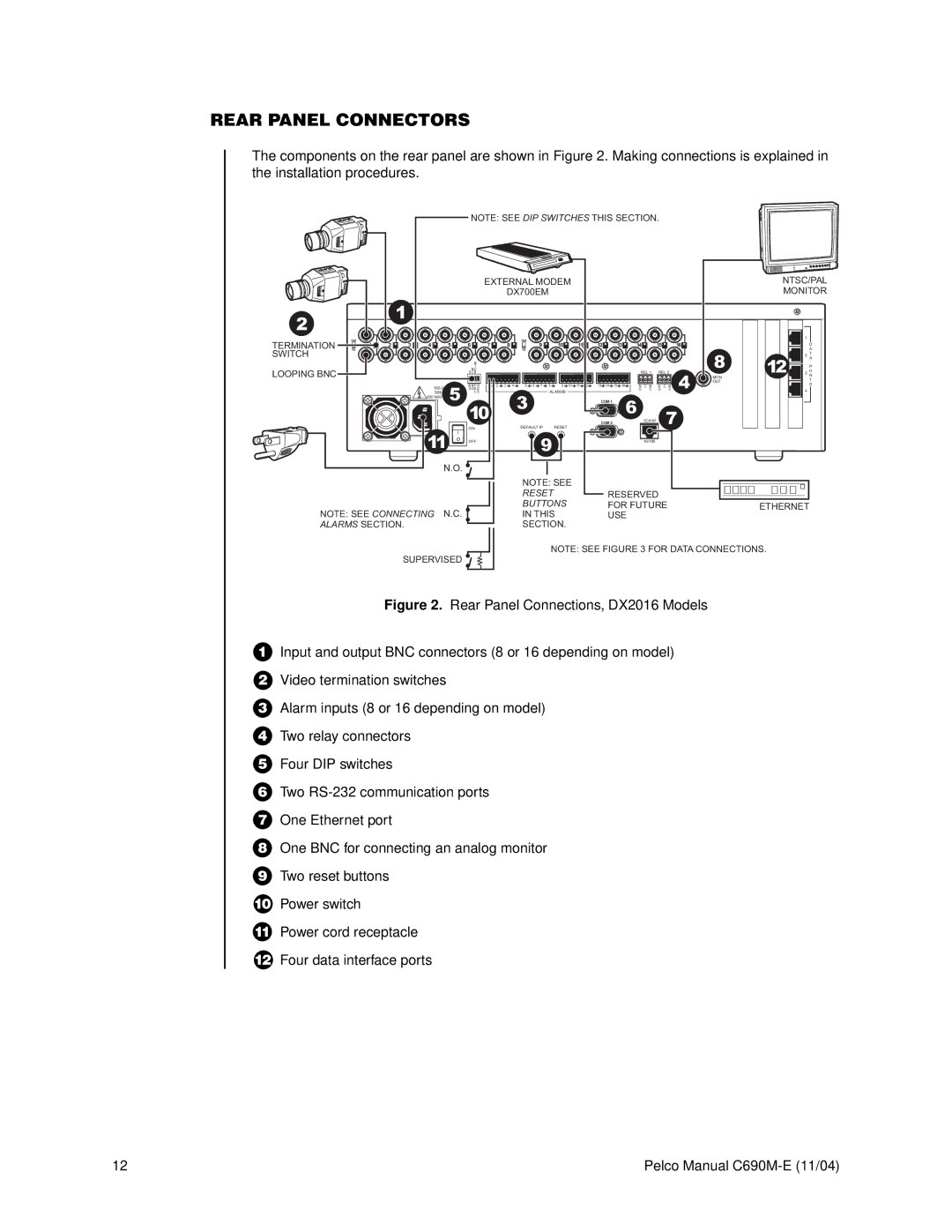
The components on the rear panel are shown in Figure 2. Making connections is explained in the installation procedures.
NOTE: SEE DIP SWITCHES THIS SECTION.
|
|
|
|
|
|
| EXTERNAL MODEM |
|
|
|
|
|
|
|
|
|
|
| NTSC/PAL | ||||||||||
|
|
|
|
|
|
|
|
|
| DX700EM |
|
|
|
|
|
|
|
|
|
|
|
|
|
| MONITOR | ||||
28 |
|
| 1 |
|
|
|
|
|
|
|
|
|
|
|
|
|
|
|
|
|
|
|
|
|
|
|
|
|
|
|
|
|
|
|
|
|
|
|
|
|
|
|
|
|
|
|
|
|
|
|
|
|
|
|
|
|
|
| |
|
|
|
|
|
|
|
|
|
|
|
|
|
|
|
|
|
|
|
|
|
|
|
|
|
|
|
| 1 |
|
| 75 |
|
|
|
|
|
|
|
|
| 75 |
|
|
|
|
|
|
|
|
|
|
|
|
|
|
|
|
|
|
TERMINATION | 1 | 2 | 3 | 4 | 5 | 6 | 7 |
|
| 8 |
| 9 |
| 10 |
| 11 |
| 12 |
| 13 | 14 |
| 15 |
| 16 |
|
|
| D |
SWITCH | HZ |
|
|
|
|
|
|
|
|
| HZ |
|
|
|
|
|
|
|
|
|
|
|
|
|
|
|
|
| A |
|
|
|
|
|
|
|
|
|
|
|
|
|
|
|
|
|
|
|
|
|
|
|
|
| 8 |
| 2 | T | |
|
|
|
|
|
|
|
|
|
|
|
|
|
|
|
|
|
|
|
|
|
|
|
|
|
|
|
| A | |
|
|
|
|
|
| N |
|
|
|
|
|
|
|
|
|
|
|
|
|
|
|
|
|
|
| 12 |
|
| |
|
|
|
|
|
| T |
|
|
|
|
|
|
|
|
|
|
|
|
|
|
|
|
|
|
|
| P | ||
|
|
|
|
|
| N C |
|
|
|
|
|
|
|
|
|
|
|
|
|
|
|
|
|
|
|
|
| O | |
LOOPING BNC |
|
|
|
|
| S C S |
|
|
|
|
|
|
|
|
|
|
|
|
|
| REL 1 | REL 2 |
|
| 3 | ||||
|
|
|
|
|
|
|
|
|
|
|
|
|
|
|
|
|
|
| 4 | MON |
| R | |||||||
|
|
|
|
|
|
|
|
|
|
|
|
|
|
|
|
|
|
|
|
|
|
|
|
| OUT |
|
| T | |
|
|
|
|
| N N P R | 1 | 2 | 3 | 4 | 5 6 | 7 | 8 | 9 | 10 | 11 | 12 | 13 14 | 15 | 16 | N | C N | N | C N |
|
| S | |||
|
|
|
|
| S O A E |
|
|
|
|
|
|
|
|
|
|
|
|
|
| O | C | O | C |
|
|
| 4 |
| |
|
|
|
|
| 50/60HZ | L S |
|
|
|
|
|
| ALARMS |
|
|
|
|
|
|
|
|
|
|
|
|
|
|
| |
|
|
|
| 200 WATTS MAX |
|
|
|
|
|
|
|
|
|
|
|
|
|
|
|
|
|
|
|
|
|
|
|
| |
|
|
|
|
| 5 |
|
|
|
|
| 3 |
|
|
|
|
|
| COM 1 |
|
|
|
|
|
|
|
|
|
|
|
|
|
|
|
|
|
|
|
|
|
|
|
|
|
|
|
|
|
| 6 |
|
|
|
|
|
|
|
| ||
|
|
|
|
|
| 10 |
|
|
|
|
|
|
|
|
|
|
|
|
|
|
|
|
|
|
|
| |||
|
|
|
|
|
|
|
|
|
|
|
|
|
|
|
|
|
|
|
|
| 7 |
|
|
|
| ||||
|
|
|
|
|
|
|
|
|
|
|
|
|
|
|
|
|
|
|
|
|
|
|
|
|
| ||||
|
|
|
|
|
|
|
|
|
|
|
|
|
|
|
|
|
| COM 2 |
|
|
| TCP/IP |
|
|
|
|
| ||
|
|
|
|
|
| ON |
|
|
|
| DEFAULT IP |
| RESET |
|
|
|
|
|
|
|
|
|
|
|
|
|
|
| |
|
|
|
| 11 | OFF |
|
|
|
|
| 9 |
|
|
|
|
|
|
|
| 10/100 |
|
|
|
|
|
|
| ||
N.O. |
NOTE: SEE CONNECTING N.C. ALARMS SECTION.
SUPERVISED
NOTE: SEE |
|
|
|
|
RESET | RESERVED |
|
|
|
|
|
| ||
BUTTONS | FOR FUTURE |
| ETHERNET | |
|
|
| ||
IN THIS | USE |
|
|
|
SECTION. |
|
|
|
|
NOTE: SEE FIGURE 3 FOR DATA CONNECTIONS.
Figure 2. Rear Panel Connections, DX2016 Models
1Input and output BNC connectors (8 or 16 depending on model)
2Video termination switches
3Alarm inputs (8 or 16 depending on model)
4Two relay connectors
5Four DIP switches
6Two RS-232 communication ports
7One Ethernet port
8One BNC for connecting an analog monitor
9Two reset buttons
10Power switch
11Power cord receptacle
12Four data interface ports
12 | Pelco Manual |