Table
Input Signals
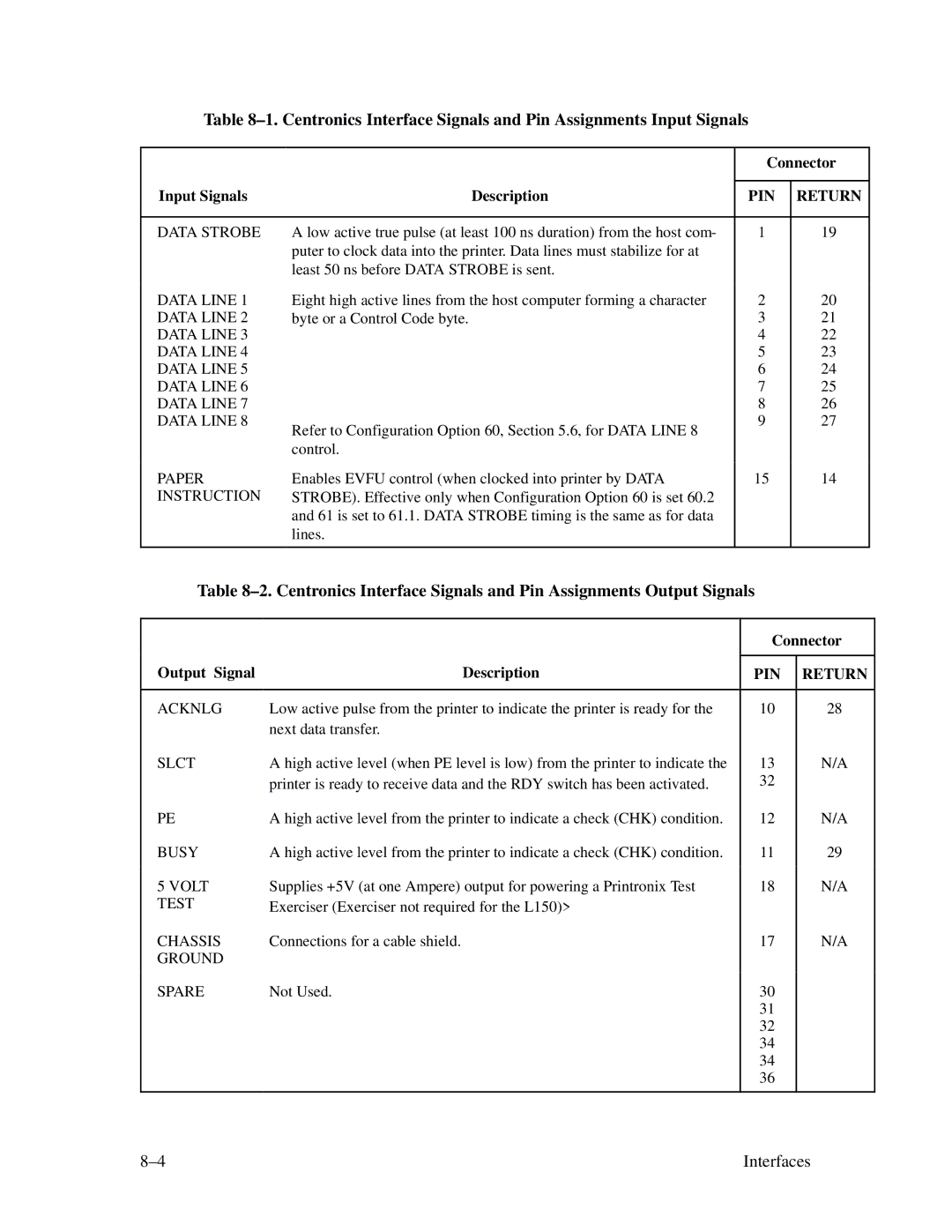
DATA STROBE
| Connector | |
|
|
|
Description | PIN | RETURN |
|
|
|
A low active true pulse (at least 100 ns duration) from the host com- | 1 | 19 |
puter to clock data into the printer. Data lines must stabilize for at |
|
|
least 50 ns before DATA STROBE is sent. |
|
|
|
|
|
DATA LINE 1 DATA LINE 2 DATA LINE 3 DATA LINE 4 DATA LINE 5 DATA LINE 6 DATA LINE 7 DATA LINE 8
PAPER INSTRUCTION
Eight high active lines from the host computer forming a character byte or a Control Code byte.
Refer to Configuration Option 60, Section 5.6, for DATA LINE 8 control.
Enables EVFU control (when clocked into printer by DATA STROBE). Effective only when Configuration Option 60 is set 60.2 and 61 is set to 61.1. DATA STROBE timing is the same as for data lines.
2
3
4
5
6
7
8
9
15
20
21
22
23
24
25
26
27
14
Table
Output Signal | Description |
Connector
PIN RETURN
ACKNLG | Low active pulse from the printer to indicate the printer is ready for the |
| next data transfer. |
SLCT | A high active level (when PE level is low) from the printer to indicate the |
| printer is ready to receive data and the RDY switch has been activated. |
PE | A high active level from the printer to indicate a check (CHK) condition. |
BUSY | A high active level from the printer to indicate a check (CHK) condition. |
5 VOLT | Supplies +5V (at one Ampere) output for powering a Printronix Test |
TEST | Exerciser (Exerciser not required for the L150)> |
CHASSIS | Connections for a cable shield. |
GROUND |
|
SPARE | Not Used. |
10
13
32
12
11
18
17
30
31
32
34
34
36
28
N/A
N/A
29
N/A
N/A
Interfaces |