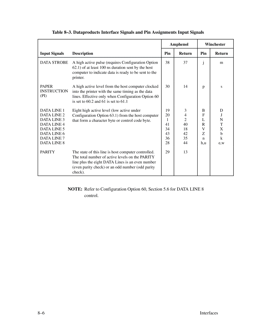
Table
Input Signals | Description |
Amphenol | Winchester | ||
|
|
|
|
Pin | Return | Pin | Return |
|
|
|
|
DATA STROBE A high active pulse (requires Configuration Option 62.1) of at least 100 ns duration sent by the host computer to indicate data is ready to be sent to the printer.
38
37
j
m
PAPER INSTRUCTION (PI)
DATA LINE 1 DATA LINE 2 DATA LINE 3 DATA LINE 4 DATA LINE 5 DATA LINE 6 DATA LINE 7 DATA LINE 8
A high active level from the host computer clocked into the printer with the same timing as the data lines. Effective only when Configuration Option 60 is set to 60.2 and 61 is set to 61.1
Eight high active level (low active under Configuration Option 63.1) from the host computer that form a character byte or control code byte.
30
19
20
1
41
34
43
36
28
14
3
4
2
40
18
42
35
44
p
B
F
L
R
V
Z n h,u
s
D
J
N
T
X b k e,w
PARITY | The state of this line is host computer controlled. |
| The total number of active levels on the PARITY |
| line plus the eight DATA Lines is an even number |
| (even parity check) or an odd number (odd parity |
| check). |
|
|
29
13
NOTE: Refer to Configuration Option 60, Section 5.6 for DATA LINE 8 control.
Interfaces |
