Page
Important Safety Instructions
For the U.K
Page
Power Supply
Placement
Before Using Cards
Maintenance
Additional Precautions
Handling CD-ROMs
How To Use This Manual
Contents
Creating and Editing Samples Sample Mode
Contents
Connecting to Your Computer via USB USB Mode
Appendices 101
Ideal combination of sound generators
Main Features
An interface that gives life to the sound
Open system architecture
Main Features
Use with other devices for even greater possibilities
Full complement of external interfaces
Panel Descriptions
Front Panel
Panel Descriptions
Pitch Bend/Modulation Lever
14 OSC1, OSC2
16 TVA
LFO DP1, LFO DP2, LFO DP3
Rear Panel
Basic Structure
Overview of the V-Synth
How the V-Synth Is Organized
Polyphony
Memory
Memory Structure
Changing Operating Modes Mode
Basic Operation of the V-Synth
Basic Touch Screen Operation
Moving the Cursor
Editing a Value
Selecting a Patch
Playing in Patch Mode
About the Patch Play Screen
Displaying Patch Play Screen
Selecting Favorite Patches Patch Palette
Press Transpose to light indicator
Transposing the Keyboard in Semitone Steps Transpose
Selecting Patches from the List
Playing Single Notes Mono
Transposing the Keyboard in Octave Units Octave Shift
Creating Smooth Pitch Changes Portamento
Playing Arpeggios Arpeggiator
Using an External Midi Keyboard to Play Arpeggios
When Using a Hold Pedal
Holding an Arpeggio
Creating an Original Arpeggio Pattern Pattern Edit
Making Arpeggiator Settings
About the Pattern Edit Window
Creating a Pattern by Playing in Real Time Real Rec
Creating a Pattern by Inputting One Step at a Time Step Rec
Playing in Patch Mode Erasing a Pattern Clear
When you are finished with step input, touch Stop
Touch Step Rec
What is the Time Trip function?
Applying Various Effects to the Sound
If Assignable is on
Mode
Usable range of the D Beam controller
Function to turn on the D Beam controller
Synchronizing Music Video While You Play Synth V-LINK
Applying an Effect by Turning a Knob Assignable Controller
Example Connections
Enter V-LINK Mode
Press V-LINK so the indicator lights
Link function Transmitted Midi message
Creating a Patch
How to Make the Patch Settings
Four Tips for Editing Patches
Copying Patch Settings Patch Copy
Initializing Patch Settings Patch Init
Patch
Pulldown menu, touch Patch Name
Naming a Patch Patch Name
Saving Patches Patch Write
Pulldown menu, touch Patch Write
Touch Execute to execute the Save operation
Auditioning the Save-Destination Patch Compare
Registering a Favorite Patch Patch Palette
Palette p
Functions of Patch Parameters
Settings Common to the Entire Patch Common
Deleting Patches Patch Delete
General
Beam/Bender
TT Pad
Matrix Ctrl
CSM1/2-PRM1 p CSM1/2-PRM2 p
Sens Matrix Control Sens
Destination 1, 2 Matrix Control Destination 1
CSM1/2-LFO-PRM1 p CSM1/2-LFO-PRM2 p
Creating a Patch Arpeggio
Tune
Modifying Waveforms OSC1/ OSC2
OSC Type
Pitch
Fat Analog
Creating a Patch Pulse Width Analog
Time PCM
Formant PCM
Mod Type
Mixing/Modulating Two Sounds Mod
Applying Various Effects to Each Note You Play COSM1/COSM2
Cosm Type
Adjusting the Volume and Pan TVA
Making Envelope Settings
Making LFO Settings
How to Apply the LFO
Setting Effects for a Patch Effect
Routing
MFX To CHO MFX Chorus Send Level
CHO Chorus On/Off Switch
REV Reverb On/Off Switch
MFX To REV MFX Reverb Send Level
Splitting the Keyboard to Play Different Sounds Split
Zone Settings Zone
Pulldown menu, touch Zone
Creating a Drum Patch Drum
Lower part of the screen, touch Drum
To save the patch you created, perform the Write operation p
Factory Settings of Each Template
Creating and Editing Samples Sample Mode
Settings Before You Sample What Is a Template?
Sampling
Setup Comp Limiter NoiseSup
Sampling Procedure
Touch Sample
Touch Sampling
When you are finished sampling, touch Stop
Select the location sample number that you wish to sample
Touch Tmpl 1-TMPL 8 to select a sampling template
Pulldown menu, touch Sample Copy
Copying a Sample Sample Copy
Pulldown menu, touch Sample Name
Touch Execute to execute the copy operation Press Exit
Touch Execute to execute the move operation Press Exit
Moving a Sample Sample Move
Pulldown menu, touch Sample Move
Pulldown menu, touch Sample Exchange
Sampling General
Setup Settings
Resampling
Sampling Type
Pre-Effect Settings
Sampling Pre-Effect
Metronome Settings
Metronome
Original Pitch
Checking Sample Information
Original Fine Tune
Editing a Sample
Common Procedure for Editing
Importing a Sample
Displaying the Sample Edit Screen
Functions Common to All Editing Screens
Start, End, and Current Settings
Adjust
Touch Edit
Zero Cross Search
Editing the Specified Region of the Sample
Basic Operation
Zoom
Cut
Zero Insert
LR-Mix
Trim Trimming
Reverse
Loop Region Settings
Region
Converting the Sample to V- Synth Data Encode
Original Tempo Setting
Displaying the Encode Screen
To Execute the Encode Operation
Selecting the Encoding Type
Touch Encode
Deleting an Event
Automatically Detecting Events
Deleting and Adding Events
Adding an Event
Access the Sample Top screen p Touch Save
Saving a Sample
Saving the System Settings Write
Settings Common to All Modes System Mode
How to Make the System Function Settings
Initializing the System Settings Init
Functions of System Parameters
Settings Common to the Entire System Common
Master
Rx Bank Receive Bank Select Switch
Band EQ 4-Band Equalizer Switch
Rx PC Receive Program Change Switch
MID 2 Gain
USB Setup
Tx Bank Transmit Bank Select Switch
Part1-16 Rx Sw Part 1-16 Receive Switch
Tx PC Transmit Program Change Switch
Switch
TT Pad/Knob
Pedal
Beam
Link Settings V-LINK
Lever
Bend Assign V-LINK Pitch Bend Assign
After Local Sw V-LINK Aftertouch Local Switch
After Assign V-LINK Aftertouch Assign
About Disk Utility
Disk-Related Functions Disk Mode
Basic Disk Utility Operations
Sorting the Files Displayed in the File List
Access the Disk Utility Menu screen p Touch Load Project
Loading a Project from Disk into the V-Synth Load Project
Upper right of the disk utility screen, touch
Importing Individual Patch or
Delete Unneeded Files Clean Project
Saving Project on Disk Save Project
Wave Files Import Files
Access the Disk Utility Menu screen p Touch Format
Initializing a Disk Format
Copying Files/Folders Copy
Functions Related to Files and Folders Tools
Moving Files/Folders Move
Deleting Files/Folders Delete
File list, select the file or folder that you want to move
Renaming a Files/Folders Rename
When you have finished inputting, touch OK to execute
Operation.Mode DiskFunctions Related-Disk
Selecting USB Storage Mode
Transferring Files to or from Your Computer Storage Mode
About USB Functions
Windows 98/98SE Users
Connecting to Your Computer via USB USB Mode
Windows Users
Windows XP/2000/Me or later Users
Canceling the USB Connection
Connecting to Your Computer via USB USB Mode
Switching the Connected Drive
Closing the USB Storage Screen
Macintosh Users
Computer
Backing Up Patch and Wave Data Project from the V-Synth
Examples of Using Storage Mode
Loading Backup Data from Your Computer into the V-Synth
Backing Up the V-Synth’s Internal Data onto Your Computer
Internal Memory
Synth Import
PC Card
Driver Installation and Settings
Exchanging Midi Messages with Your Computer Midi Mode
What is the USB Midi Driver?
Transmitting Data to an External Midi Device Data Transfer
Other Functions
Other Functions
Touch Execute to execute the Factory Reset
Reset to Default Factory Settings Factory Reset
Touch Factory Reset
Viewing Various Information Info
Touch Calibration
Adjusting the Sensitivity of the Touch Screen
Displaying the Calibration Menu Screen
Calibration Menu screen, touch Touch Screen
Adjusting the Sensitivity of the D Beam Controller
Adjusting the Sensitivity of the Time Trip Pad
100
101
Appendices
Common Group p
Parameter List
Patch Parameters
102
Parameter List OSC1/OSC2 Group p
103
Parameter Value Fat Analog
Parameter List
104
Time PCM
105
Mod Group p
COSM1/COSM2 Group p
Mod Type
Parameter List TVA Group p
106
107
Parameter List Effect Group p
Parameter Value Routing
Parameter Value Master
System Parameters
108
Part Midi
TT Pad/Knob
Parameter List Controller Group p
109
Beam
110
Parameter List Link Group p
Lever
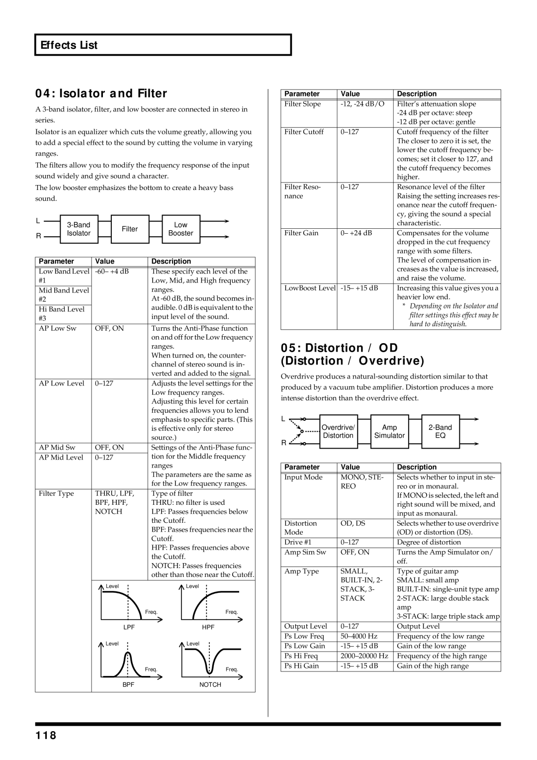
Overdrive / Distortion
Cosm List
Cosm Parameters
Wave Shape
Resonator
Amp Simulator
Speaker Simulator
1st order SideBandFilter
Dual Filter
2nd order SideBandFilter
Comb Filter
113
114
Dynamic TVF
Polyphonic Compressor
Cutoff
Lo-Fi Processor
Polyphonic Limiter
Frequency Shifter
115
116
Effects List
MFX Parameters
DS / OD
Resonant Filter
Parametric EQ Parametric Equalizer
Graphic EQ Graphic Equalizer
Effects List
Distortion / OD Distortion / Overdrive
Isolator and Filter
118
119
Specifications of each Speaker Type
Amp Simulator Guitar Amp Simulator
Type Cabinet Speaker Microphone
120
Auto Wah
Humanizer
LPF, BPF
121
Dynamic Processor Stereo Dynamic Processor
Tape Echo Simulator
+M+L
REO, Alter
Stereo Delay
122
Nate
Reverse Delay
Multi Tap Delay
123
Vocal Echo
Band Pass Delay
Delay Pan Type Values Dly
124
Digital Chorus
Analog Delay→ Chorus
125
Analog Flanger
Space Chorus
Hexa Chorus
126
Step Flanger
Boss Flanger
127
128
Analog Phaser
Digital Phaser
4STAGE
Tremolo/Auto Pan
Rotary
129
28 OD/DS→ Cho/Flg Overdrive/ Distortion→ Chorus/Flanger
Stereo Pitch Shifter
130
30 Cho/Flg→ Delay Chorus/Flanger→ Delay
29 OD/DS→ Delay Overdrive/Distortion→ Delay
131
31 Enh→ Cho/Flg Enhancer→ Chorus/Flanger
32 Enh→ Delay Enhancer→ Delay
132
133
Vocal Multi
Guitar Multi
LIMITER, DE
Bass Multi
134
Keyboard Multi
Rhodes Multi
135
136
Radio Tuning
Phonograph
LP, EP, SP
Pseudo Stereo
Bit Rate Converter
137
Chorus Type
Chorus Parameters
Reverb Parameters
Chorus Parameters
Room
139
Hall
140
141
Garage
142
Non-Linear
Delay
143
144
Problems Related to the V-Synth
Troubleshooting
145
Troubleshooting
Problems Related to the USB Driver Windows
146
Deleting Incorrect Device Information
147
Problems Related to the USB Driver Macintosh
148
Message List
Error Screens
149
Message List
150
Message Boxes
151
About Midi
About Midi Connectors
Midi Channels and Multi-timbral Sound Generators
Midi Implementation
153
Midi Implementation
154
Master Coarse Tuning
Master Volume
Master Fine Tuning
155
Data Request 1RQ1 11H
Scale/Octave Tuning Adjust
156
Data Set DT1 12H
157
158
Identity Reply Message
System
Setup
159
Patch
System Controller
160
Patch Common
161
MFX-SEND, CHO-SEND, REV-SEND MFX-PRM1, MFX-PRM2, MFX-PRM3
162
Patch MFX
Patch Chorus
163
Patch Reverb
164
Patch Oscillator
165
Patch Envelope
Patch LFO
166
Patch Cosm
Patch Controller
167
Patch Arpeggio
Midi Implementation Supplementary Material
168
Example2 Getting the data RQ1 of Patch MFX in PATCH003
Example1 Setting Chorus Type of Patch to Chorus 1 DT1
169
Example3 Getting Temporary Patch Part 1 data RQ1
Just Temperament Tonic of C
170
Equal Temperament
Arabian Scale
Midi Implementation Chart
171
Specifications
172
173
Index
Assignable
Hold
Index
174
LFO
175
ON/OFF
176
12, 14
177
Time Trip
Installing the PC Card Protector
178
For the USA
179
For EU Countries
For Canada
Information