Technical data and characteristics
14.1 Explanations of the formula abbreviations
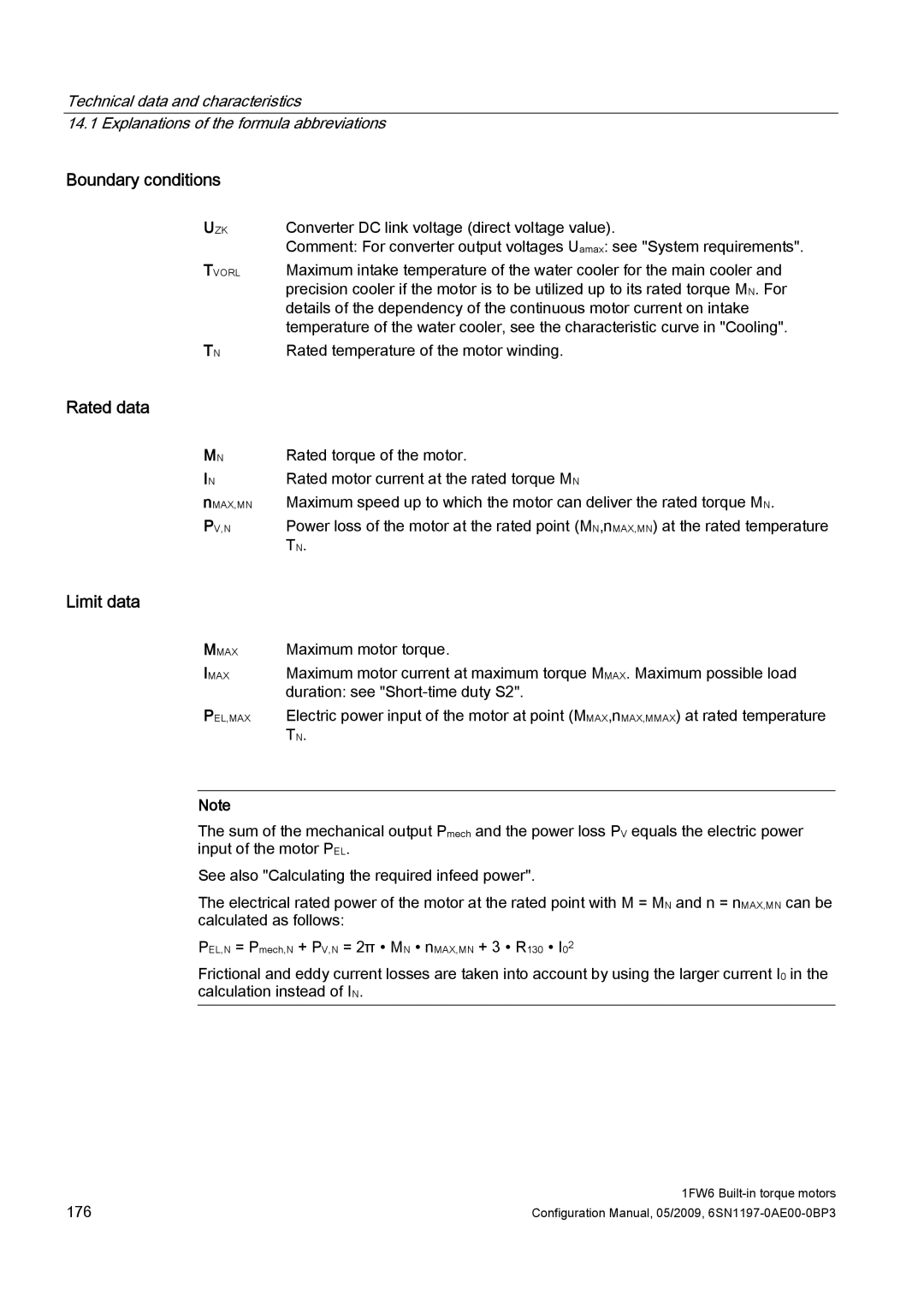
Boundary conditions
UZK
TVORL
TN
Converter DC link voltage (direct voltage value).
Comment: For converter output voltages Uamax: see "System requirements".
Maximum intake temperature of the water cooler for the main cooler and precision cooler if the motor is to be utilized up to its rated torque MN. For details of the dependency of the continuous motor current on intake temperature of the water cooler, see the characteristic curve in "Cooling".
Rated temperature of the motor winding.
Rated data
MN
IN
nMAX,MN PV,N
Rated torque of the motor.
Rated motor current at the rated torque MN
Maximum speed up to which the motor can deliver the rated torque MN.
Power loss of the motor at the rated point (MN,nMAX,MN) at the rated temperature TN.
Limit data
MMAX
IMAX
PEL,MAX
Maximum motor torque.
Maximum motor current at maximum torque MMAX. Maximum possible load duration: see
Electric power input of the motor at point (MMAX,nMAX,MMAX) at rated temperature TN.
Note
The sum of the mechanical output Pmech and the power loss PV equals the electric power input of the motor PEL.
See also "Calculating the required infeed power".
The electrical rated power of the motor at the rated point with M = MN and n = nMAX,MN can be calculated as follows:
PEL,N = Pmech,N + PV,N = 2π ∙ MN ∙ nMAX,MN + 3 ∙ R130 ∙ I02
Frictional and eddy current losses are taken into account by using the larger current I0 in the calculation instead of IN.
176 | 1FW6 |
Configuration Manual, 05/2009, |
