Installation drawings/Dimension drawings 15.2 Explanation of installation drawings
15.2Explanation of installation drawings
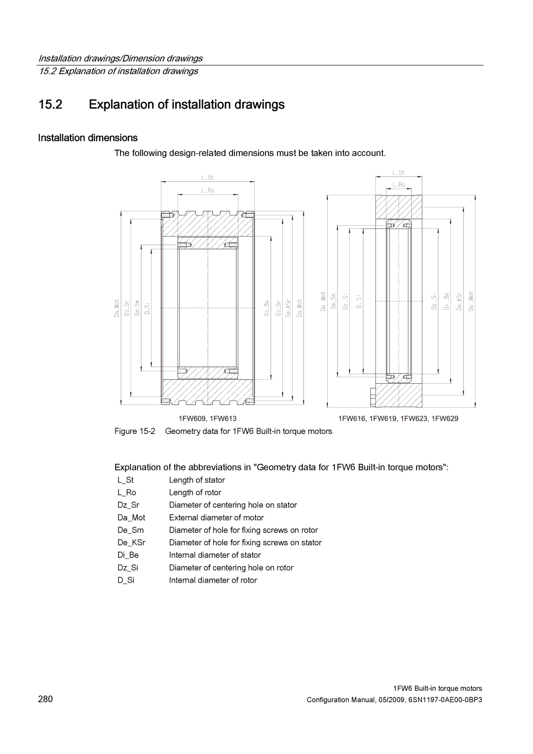
Installation dimensions
The following
Figure 15-2 Geometry data for 1FW6 Built-in torque motors
Explanation of the abbreviations in "Geometry data for 1FW6
L_St | Length of stator |
L_Ro | Length of rotor |
Dz_Sr | Diameter of centering hole on stator |
Da_Mot | External diameter of motor |
De_Sm | Diameter of hole for fixing screws on rotor |
De_KSr | Diameter of hole for fixing screws on stator |
Di_Be | Internal diameter of stator |
Dz_Si | Diameter of centering hole on rotor |
D_Si | Internal diameter of rotor |
280 | 1FW6 |
Configuration Manual, 05/2009, |