Configuring the motor 5.2 Example(s)
transitional phases between acceleration/deceleration and the resulting angle changes are not taken into account.
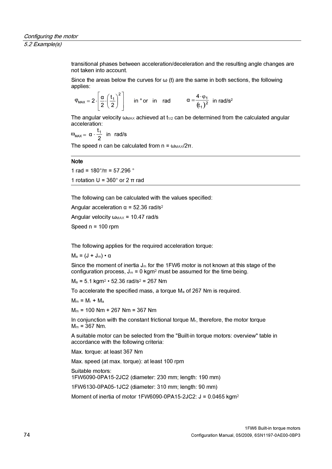
Since the areas below the curves for ω (t) are the same in both sections, the following applies:
LQRULQ 


 LQ
LQ 


The angular velocity ωMAX achieved at t1/2 can be determined from the calculated angular acceleration:
LQ
The speed n can be calculated from n = ωMAX/2π.
Note
1 rad = 180°/π = 57.296 °
1 rotation U = 360° or 2 π rad
The following can be calculated with the values specified:
Angular acceleration α = 52.36 rad/s2
Angular velocity ωMAX = 10.47 rad/s
Speed n = 100 rpm
The following applies for the required acceleration torque: Ma = (J + Jm) • α
Since the moment of inertia Jm for the 1FW6 motor is not known at this stage of the configuration process, Jm = 0 kgm2 must be assumed for the time being.
Ma = 5.1 kgm2 • 52.36 rad/s2 = 267 Nm
To accelerate the specified mass, a torque Ma of 267 Nm is required. Mm = Mr + Ma
Mm = 100 Nm + 267 Nm = 367 Nm
In conjunction with the constant frictional torque Mr, therefore, the motor torque Mm = 367 Nm.
A suitable motor can be selected from the
Max. torque: at least 367 Nm
Max. speed (at max. torque): at least 100 rpm
Suitable motors:
Moment of inertia of motor
74 | 1FW6 |
Configuration Manual, 05/2009, |