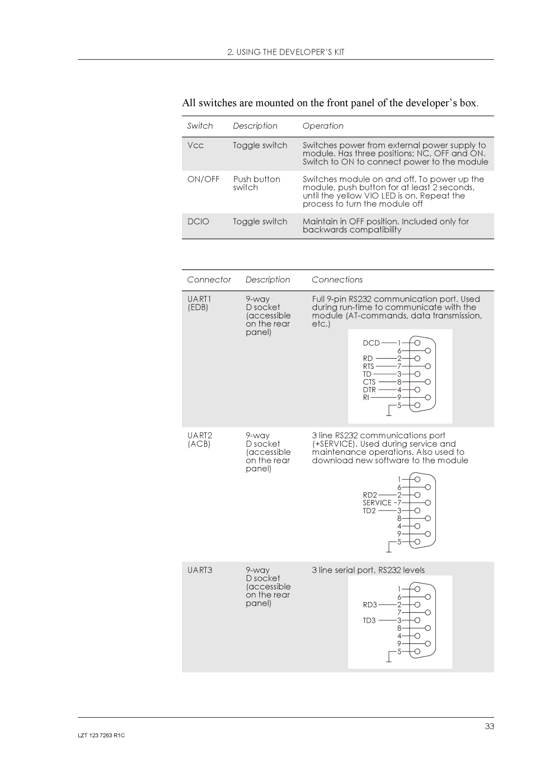
2. USING THE DEVELOPER’S KIT
All switches are mounted on the front panel of the developer’s box.
Switch | Description | Operation |
|
|
|
Vcc | Toggle switch | Switches power from external power supply to |
|
| module. Has three positions; NC, OFF and ON. |
|
| Switch to ON to connect power to the module |
ON/OFF | Push button | Switches module on and off. To power up the |
| switch | module, push button for at least 2 seconds, |
|
| until the yellow VIO LED is on. Repeat the |
|
| process to turn the module off |
|
|
|
DCIO | Toggle switch | Maintain in OFF position. Included only for |
|
| backwards compatibility |
|
|
|
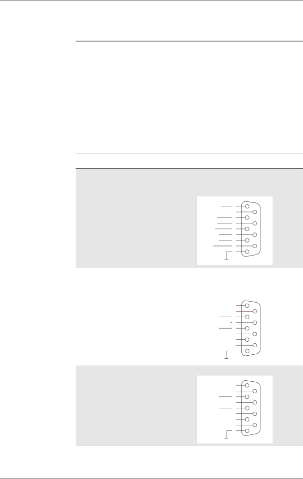
Connector | Description | Connections |
|
UART1 | Full | ||
(EDB) | D socket | during | |
| (accessible | module | |
| on the rear | etc.) |
|
| panel) |
|
|
|
| DCD | 1 |
|
|
| 6 |
|
| RD | 2 |
|
| RTS | 7 |
|
| TD | 3 |
|
| CTS | 8 |
|
| DTR | 4 |
|
| RI | 9 |
|
|
| 5 |
UART2 | 3 line RS232 communications port | ||
(ACB) | D socket | (+SERVICE). Used during service and | |
| (accessible | maintenance operations. Also used to | |
| on the rear | download new software to the module | |
| panel) |
|
|
|
|
| 1 |
|
|
| 6 |
|
| RD2 | 2 |
|
| SERVICE | 7 |
|
| TD2 | 3 |
|
|
| 8 |
|
|
| 4 |
|
|
| 9 |
|
|
| 5 |
UART3 | 3 line serial port. RS232 levels | ||
| D socket |
|
|
| (accessible |
| 1 |
| on the rear |
| 6 |
| panel) | RD3 | 2 |
|
|
| 7 |
|
| TD3 | 3 |
|
|
| 8 |
4
9
5
33
LZT 123 7263 R1C