GM47/GM48 INTEGRATOR’S MANUAL
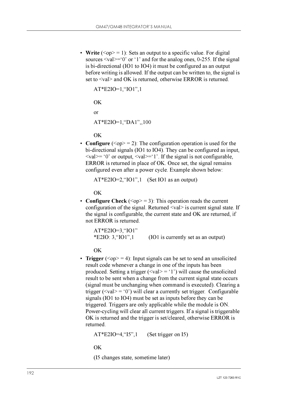
•Write (<op> = 1): Sets an output to a specific value. For digital sources <val>=‘0’ or ‘1’ and for the analog ones,
AT*E2IO=1,“IO1”,1
OK or AT*E2IO=1,“DA1”,,100
OK
•Configure (<op> = 2): The configuration operation is used for the
AT*E2IO=2,“IO1”,1 (Set IO1 as an output)
OK
•Configure Check (<op> = 3): This operation reads the current configuration of the signal. Returned <val> is current signal state. If the signal is configurable, the current state and OK are returned, if not ERROR is returned.
AT*E2IO=3,“IO1” |
|
*E2IO: 3,“IO1”,1 | (IO1 is currently set as an output) |
OK
•Trigger (<op> = 4): Input signals can be set to send an unsolicited result code whenever a change in one of the inputs has been produced. Setting a trigger (<val> = ‘1’) will cause the unsolicited result to be sent when a change from the current signal state occurs (signal must be unchanging when command is executed). Clearing a trigger (<val> = ‘0’) will clear a currently set trigger. Configurable signals (IO1 to IO4) must be set as inputs before they can be triggered. Triggers are only applicable while the module is ON.
AT*E2IO=4,“I5”,1 | (Set trigger on I5) |
OK
(I5 changes state, sometime later)
192
LZT 123 7263 R1C
