MIX 56 User Manual | 2 Installation |
Step Action
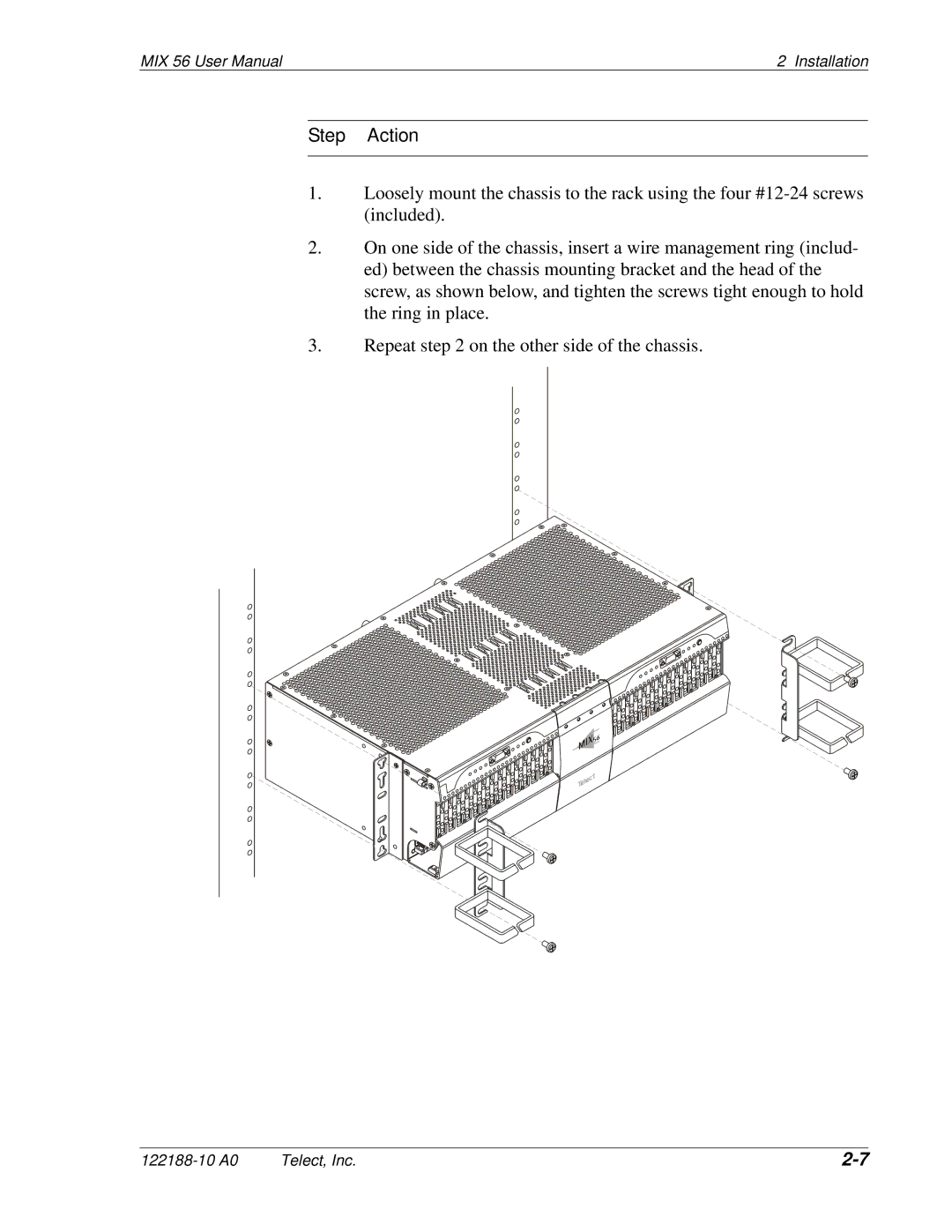
1.Loosely mount the chassis to the rack using the four
2.On one side of the chassis, insert a wire management ring (includ- ed) between the chassis mounting bracket and the head of the screw, as shown below, and tighten the screws tight enough to hold the ring in place.
3.Repeat step 2 on the other side of the chassis.
Telect, Inc. |