MIX 56 User Manual | 4 Software Operation |
Restoring to the Factory configuration also disables security and resets the System Interfaces screen. Restoring to the Factory configuration does not change any of the three NVRam saved configurations.
Restoring the entire NVRam configuration from a file restores all three of the saved configurations plus restoring all the settings of the Security screen, Alarm Threshold screen, System Interface screen, and Update Flash screen.
ALERT
ALERT! Restoring the entire NVRam from a file or restoring to the Factory configuration resets the System Interfaces screen which includes the IP address, Subnet Mask address, and the Craft Port’s baud rate. This has the possibility of killing your communications link.
The Factory configuration does not have an IP address or Sub- net Mask address. If you restore this configuration remotely, you will not be able to reconnect to the system until the ad- dresses are added through the local Craft Interface via the Craft port.
The Factory configuration resets the local Craft Port’s baud rate to 9600.
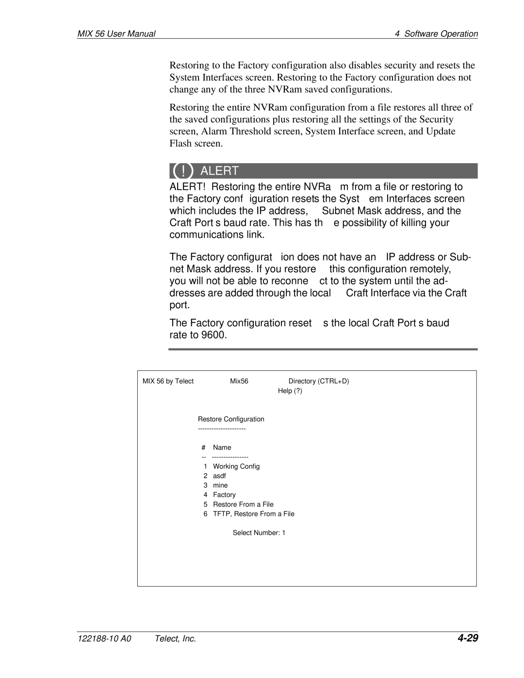
MIX 56 by Telect | Mix56 | Directory (CTRL+D) |
|
| Help (?) |
Restore Configuration |
| |
| ||
# | Name |
|
| ||
1 | Working Config |
|
2 | asdf |
|
3 | mine |
|
4 | Factory |
|
5 | Restore From a File |
|
6 | TFTP, Restore From a File |
|
Select Number: 1
Telect, Inc. |