Manuals
/
Teledyne
/
Household Appliance
/
Carbon Monoxide Alarm
Teledyne
300M
instruction manual
2 Carbon Monoxide Analyzer
Models:
300M
1
17
123
123
Download
123 pages
13.29 Kb
14
15
16
17
18
19
20
21
Troubleshooting
Specifications
Install
Parts list
1 Pneumatic Diagram
Gas Alarms
Password
Wiring
Warranty
Maintenance
Page 17
Image 17
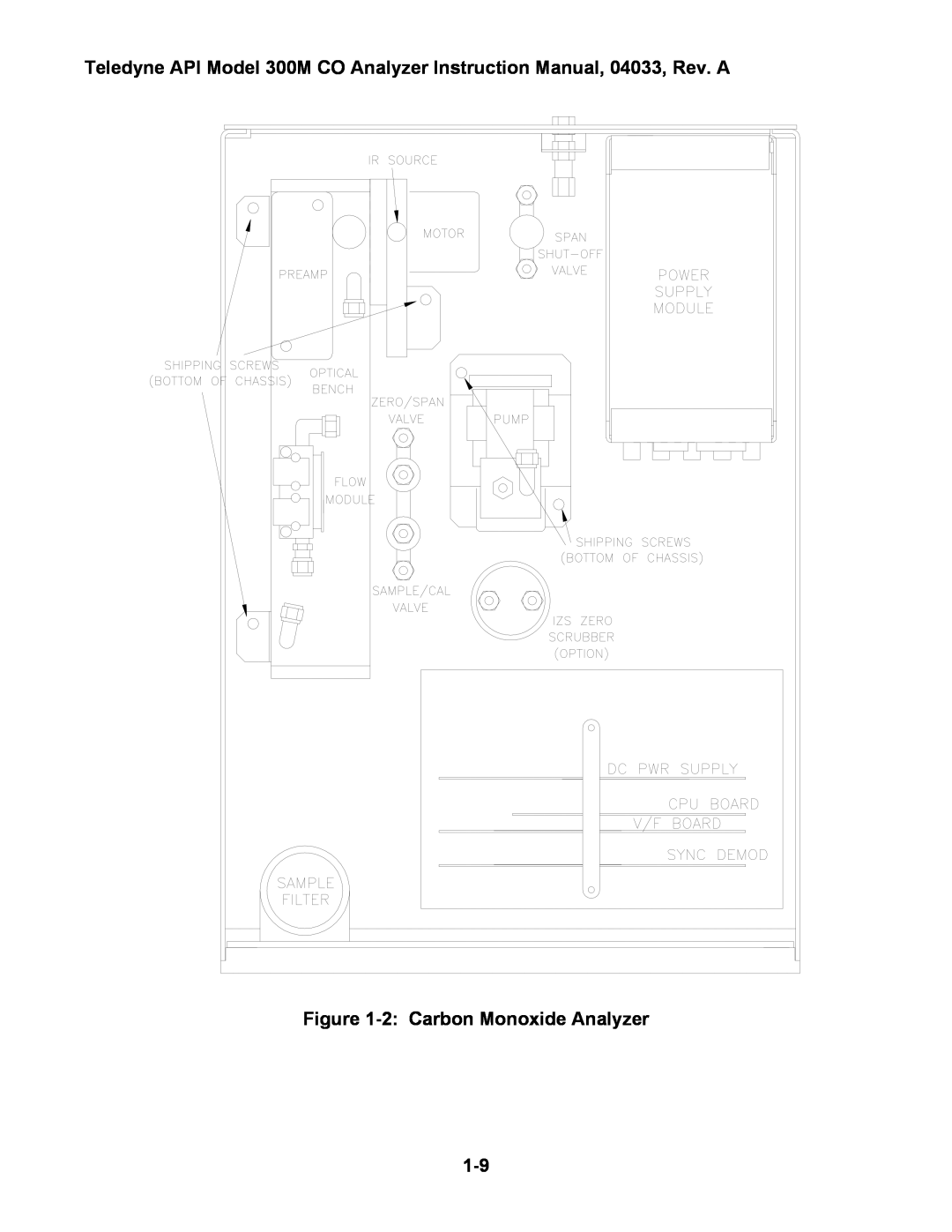
Teledyne API Model 300M CO Analyzer Instruction Manual, 04033, Rev. A
Figure
1-2:
Carbon Monoxide Analyzer
1-9
Page 16
Page 18
Page 17
Image 17
Page 16
Page 18
Contents
TOLL-FREE FAX TEL
T-API 6565 NANCY RIDGE DRIVE SAN DIEGO, CA
MODEL 300M CARBON MONOXIDE ANALYZER
04033
and in the manner described in this manual
SAFETY MESSAGES
The analyzer should only be used for the purpose
LIST OF FIGURES
TABLE OF CONTENTS
LIST OF TABLES
VIII
4 SETUP MODE
3 PERFORMANCE TESTING
5 DIAGNOSTICS
6 HANDLING WARNINGS
10 TROUBLESHOOTING
9 ADJUSTMENTS
8 CALIBRATION
10-1
12 SPARE PARTS LISTS
11 ROUTINE MAINTENANCE
12-1
232 INTERFACE
LIST OF FIGURES
viii
LIST OF TABLES
WARRANTY POLICY 02024c
1.2 Warranty
1 INTRODUCTION
1.1 Preface
TERMS AND CONDITIONS
1.3 Principle of Operation
Figure 1-1 Pneumatic Diagram
1.4 Specifications
Leak check all fittings with soap solution
1.5 Installation and Overview
lift and carry the Model 300M
suitable vent outside the analyzer area
Power plug must have ground lug
Page
Figure 1-2 Carbon Monoxide Analyzer
1-10
1.6 Electrical and Pneumatic Connections
1.6.1 Electrical Connections
1.6.2 Remote Contact Closures Zero/Span Inputs
1.6.3 Status Outputs Optional
1.6.5 Pneumatic System
1.6.4 RS-232
Table 1-1 Status Outputs
1-12
1.6.7 Zero/Span Valve Connections
1.6.6 Sample Gas Connection
1.6.8 Exhaust Connections
sample gas connections
1-14
Figure 1-4 Rear Panel Pneumatic Connections
1-15
1.7 Operation Verification
1-16
Table 1-2 Final Test and Calibration Values
Factory Installed Options
Option Installed
1.8.1 Rack Mount With Slides
1.8 Options
1.8.2 Span Valve
1-17
1-18
INTENTIONALLY BLANK
2.1.3 E2ROM Backup Of Software Configuration
2.1 Key Features
2 OPERATION
2.1.1 CO Readout
Table 2-1 Password Levels
2.1.7 Password Protection
2.1.5 Data Acquisition DAS
2.1.6 RS-232Interface
2.2.1 Front Panel Display
2.2 Front Panel
Figure 2-1 Model 300M Front Panel
Meaning
Table 2-2 System Modes
Mode
Meaning
Table 2-3 Test Measurements
Test Message
Table 2-4 Warning Messages
2.2.2 Programmable Push Buttons
Figure 2-2 Illustration of Normal Display
2.2.3 Status LED’s
Meaning
Table 2-5 Status LED’s
State
INTENTIONALLY BLANK
2-10
3.1 Manual Zero/Span Check
3 PERFORMANCE TESTING
3.1.1 Zero Check
span gas into the analyzer
3.1.2 Span Check
3.1.3 Dual Range Calibration
3.3 Zero/Span Valves Option
3.2 Span Valve Option
3.4 Automatic Zero/Span Check
The programmed start time must be a minimum of
see Section 4.3 and 4.4 for setting present time
5 minutes later than the present time
compute the carbon monoxide reading
Page
Table 3-1 Calibration Controls
to be established
least
3.8 Power-OnHold Off
3.7 Remote Zero/Span Check or Adjustment RS-232
3.9 Hold Off
3-10
4.1 Setup Mode Operation
4 SETUP MODE
4.5 Adjusting the Clock Speed
4.3Setting the Time-of-Day
4.4 Setting the Date
4.6.1 Single Range Mode SNGL
4.6 Setting the CO Concentration Range
4.6.2 Dual Range Mode DUAL
4.6.3 Auto Range Mode AUTO
4.8 Setting the RS-232Baud Rate
4.7 Setting the Analog Output Offset
4.9 Setting the Analyzer I.D
4.10 Disabling the Calibration Password
4.11.1 Data Channels
4.11 Data Acquisition System DAS
4.12 Software Configuration
4.13.1 Summary of Setup Functions
4.13 Gas Alarms
Default
Table 4-1 Setup Functions
Button Sequence
Function
Default
Table 4-1 Setup Functions Continued
Button Sequence
Function
INTENTIONALLY BLANK
4-10
5.1 Test Measurements
5 DIAGNOSTICS
Table 5-1 Diagnostic Tests
5.2 Diagnostic Tests
table continued
5.2.1 Signal I/O
Table 5-2 I/O Signals
Signal
Table 5-2 I/O Signals Continued
table continued
Control
Signal
Table 5-2 I/O Signals Continued
table continued
Control
Table 5-2 I/O Signals Continued
5.2.2 Analog Output Test
5.2.3 Electric Test
Table 5-3 M300M Variables
5.3 M300M Internal Variables
INTENTIONALLY BLANK
6 HANDLING WARNINGS
INTENTIONALLY BLANK
7 RS-232COMMUNICATIONS
Table 7-1 RS-232Port Setup - Front Panel
Table 7-2 RS-232Message Types
7.1 DAS Reporting
Page
7.2 Warnings
Warning Message Cleared
Table 7-3 RS-232Warning Message Clear Commands
Command
Table 7-4 Status Reports
7.3 Status/Control
when the analyzer is in the sample mode
Table 7-5 Control Commands
Table 7-6 Diagnostic Commands
7.4 Diagnostics
Table 7-7 Diagnostic Reports
the analyzer is in sample mode
7.5 Test Measurements
7-10
Table 7-8 Test Measurement Request Commands
Command
Test Measurement
7-11
7.6 Viewing and Modifying Variables
7-12
Table 7-9 RS-232Variable Names
8.1 Required Equipment and Gas Standards
8 CALIBRATION
Figure 8-2 Inlet Venting Recommendations
Figure 8-1 Gas Generation System
Qv × L = Qa × D
8.2 Multi-PointCalibration
8.2.1Procedure
Page
Page
8.3 Zero/Span Checking
INTENTIONALLY BLANK
9.1.1 Box Temperature Limits
9 ADJUSTMENTS
9.1 Power Supply Board Adjustment
Figure 9-1:M300M Electrical Block Diagram
the value on the voltmeter will remain constant
9.2 A/D - D/A Calibration Procedure
Page
9.4 Output Voltage Range Changes
9.3 Dark Current Signal Adjust Procedure
To adjust analog recorder offset, see Section
9.5 Flow Readout Adjustment
9.7 CPU
9.6 DC Power Supply
INTENTIONALLY BLANK
10-1
10 TROUBLESHOOTING
10.1 Overview
10-2
10.2.1 Checking the Power Sub-Systems
10.2.2 Checking the CPU and Display
10.3 Troubleshooting Using Warning Messages
10.2.3Checking the Keyboard
10-3
10-4
Table 10-1 Warning Messages
Warning Message
Meaning
10-5
10.4 Troubleshooting Using Test Function Values
10-6
Table 10-2 Test Function Values
Test Function
Meaning
10.5.1Noisy or Unstable Readings at Zero
10.5 Troubleshooting Dynamic Problems
10.5.2Noisy, Unstable, or Non-LinearSpan Readings
10.5.3Slow Response to Changes in Concentration
10.5.5Cannot Zero or Cannot Dynamic Zero
10.6.1 Troubleshooting Flow Problems
10.5.6Cannot Span or Cannot Dynamic Span
10-8
Flow is zero
Hazardous voltages present - use caution
Low Flow
High Flow
Sample Temperature
10.6.2 Troubleshooting Temperature Problems
Optical Bench Temperature
Gas Filter Wheel Temperature
Hazardous voltages present - use caution
10.6.3 Checking the V/F Card
10-11
10-12
Table 10-3 V/F Board Jumpers - Factory Settings
10-13
10.6.3.1 Analog Inputs
10.6.3.2 Digital to Analog Converters
10-14
10.6.4 Checking the DC Power Supply Board
10.6.3.3 Digital I/O Lines
10-15
10.6.5 Checking the Synchronous Demodulator Board
Figure 10-1 Opto Pickup Waveform
10.6.6 Checking the Opto Interrupter
Figure 10-2 Detector Waveform
10-16
10-17
10.6.7 Flow/Pressure Sensor
10-18
10.7 Warranty/Repair Questionnaire
11.1 Model 300M Maintenance Schedule
11 ROUTINE MAINTENANCE
Table 11-1 Maintenance Schedule
11-1
11.3.1 Using a Leak Checker
11.2Replacement of Sample Filter
11.3Leak Checking
Do not exceed 15 PSI of pressure
11.3.2 Leak Self Test
the solution may enter and contaminate the cell
vacuum. This may cause damage to the analyzer
Use only bubbles, not liquid
INTENTIONALLY BLANK
11-4
12-1
12 SPARE PARTS LISTS
12.1 Spare parts for CE Mark units
12.3 Model 300M Spare parts kit for one unit
12.2 Model 300M Expendables kit
Includes
12-2
Includes
12.4 Model 300M Level 1 parts kit for ten units
12-3
Signal
Connectors
Cables & Adapters come in 4 general types
12-4
12-5
Wiring
12-6
Troubleshooting the modem connection
ENABLE MODEM TRANSMISSION
Drawing Number
APPENDIX B Electrical drawing index
Title
12-7
Top
Page
Image
Contents