Teledyne API Model 300M CO Analyzer Instruction Manual, 04033, Rev. A
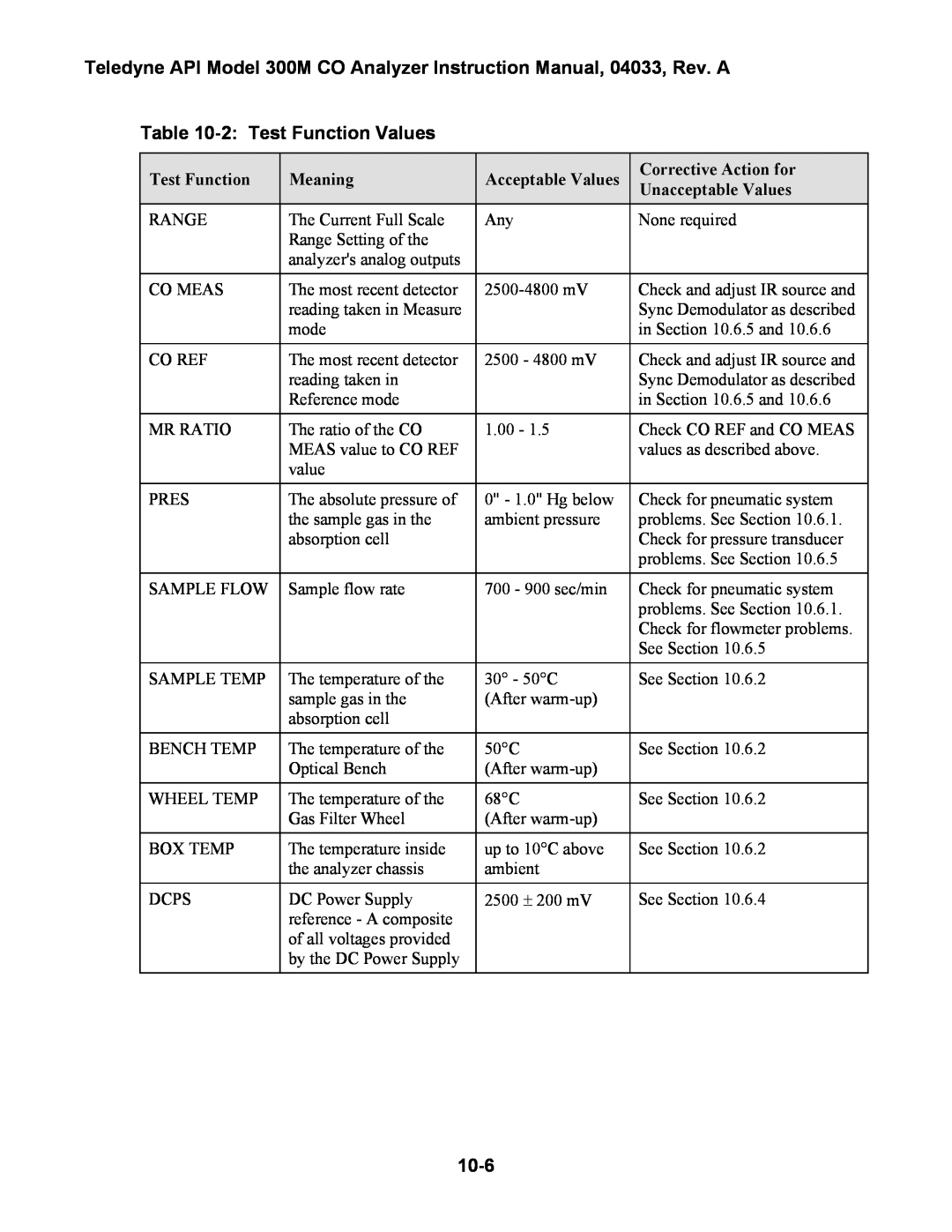
Table 10-2: Test Function Values
Test Function | Meaning | Acceptable Values | Corrective Action for | |
Unacceptable Values | ||||
|
|
| ||
RANGE | The Current Full Scale | Any | None required | |
| Range Setting of the |
|
| |
| analyzer's analog outputs |
|
| |
|
|
|
| |
CO MEAS | The most recent detector | Check and adjust IR source and | ||
| reading taken in Measure |
| Sync Demodulator as described | |
| mode |
| in Section 10.6.5 and 10.6.6 | |
|
|
|
| |
CO REF | The most recent detector | 2500 - 4800 mV | Check and adjust IR source and | |
| reading taken in |
| Sync Demodulator as described | |
| Reference mode |
| in Section 10.6.5 and 10.6.6 | |
|
|
|
| |
MR RATIO | The ratio of the CO | 1.00 - 1.5 | Check CO REF and CO MEAS | |
| MEAS value to CO REF |
| values as described above. | |
| value |
|
| |
|
|
|
| |
PRES | The absolute pressure of | 0" - 1.0" Hg below | Check for pneumatic system | |
| the sample gas in the | ambient pressure | problems. See Section 10.6.1. | |
| absorption cell |
| Check for pressure transducer | |
|
|
| problems. See Section 10.6.5 | |
|
|
|
| |
SAMPLE FLOW | Sample flow rate | 700 - 900 sec/min | Check for pneumatic system | |
|
|
| problems. See Section 10.6.1. | |
|
|
| Check for flowmeter problems. | |
|
|
| See Section 10.6.5 | |
|
|
|
| |
SAMPLE TEMP | The temperature of the | 30° - 50°C | See Section 10.6.2 | |
| sample gas in the | (After |
| |
| absorption cell |
|
| |
|
|
|
| |
BENCH TEMP | The temperature of the | 50°C | See Section 10.6.2 | |
| Optical Bench | (After |
| |
|
|
|
| |
WHEEL TEMP | The temperature of the | 68°C | See Section 10.6.2 | |
| Gas Filter Wheel | (After |
| |
|
|
|
| |
BOX TEMP | The temperature inside | up to 10°C above | See Section 10.6.2 | |
| the analyzer chassis | ambient |
| |
DCPS | DC Power Supply | 2500 ± 200 mV | See Section 10.6.4 | |
| reference - A composite |
|
| |
| of all voltages provided |
|
| |
| by the DC Power Supply |
|
|
