Teledyne 300M instruction manual

Models: 300M

1 123
Download 123 pages 13.29 Kb
Page 90
Image 90

Teledyne API Model 300M CO Analyzer Instruction Manual, 04033, Rev. A

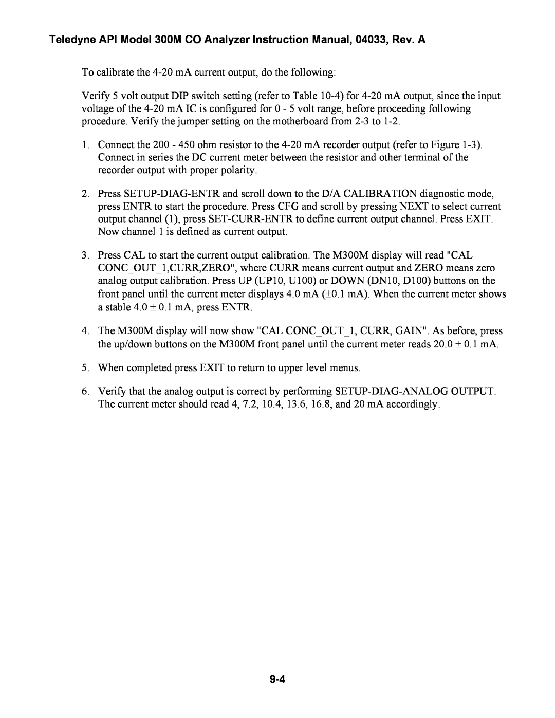
To calibrate the 4-20 mA current output, do the following:

Verify 5 volt output DIP switch setting (refer to Table 10-4)for 4-20 mA output, since the input voltage of the 4-20 mA IC is configured for 0 - 5 volt range, before proceeding following procedure. Verify the jumper setting on the motherboard from 2-3 to 1-2.

1.Connect the 200 - 450 ohm resistor to the 4-20 mA recorder output (refer to Figure 1-3). Connect in series the DC current meter between the resistor and other terminal of the recorder output with proper polarity.

2.Press SETUP-DIAG-ENTR and scroll down to the D/A CALIBRATION diagnostic mode, press ENTR to start the procedure. Press CFG and scroll by pressing NEXT to select current output channel (1), press SET-CURR-ENTR to define current output channel. Press EXIT. Now channel 1 is defined as current output.

3.Press CAL to start the current output calibration. The M300M display will read "CAL CONC_OUT_1,CURR,ZERO", where CURR means current output and ZERO means zero analog output calibration. Press UP (UP10, U100) or DOWN (DN10, D100) buttons on the front panel until the current meter displays 4.0 mA (±0.1 mA). When the current meter shows a stable 4.0 ± 0.1 mA, press ENTR.

4.The M300M display will now show "CAL CONC_OUT_1, CURR, GAIN". As before, press the up/down buttons on the M300M front panel until the current meter reads 20.0 ± 0.1 mA.

5.When completed press EXIT to return to upper level menus.

6.Verify that the analog output is correct by performing SETUP-DIAG-ANALOG OUTPUT. The current meter should read 4, 7.2, 10.4, 13.6, 16.8, and 20 mA accordingly.
9-4

Page 90
Image 90
Teledyne 300M instruction manual