Teledyne API Model 300M CO Analyzer Instruction Manual, 04033, Rev. A
APPENDIX A Tips on connecting the Teledyne API analyzer
Teledyne API analyzers use the
The problem centers around two areas. First is the physical incompatibility of connectors. Second is the wiring of the connectors. This Note will attempt to provide some guidelines for connecting the Teledyne API analyzers to a variety of other equipment
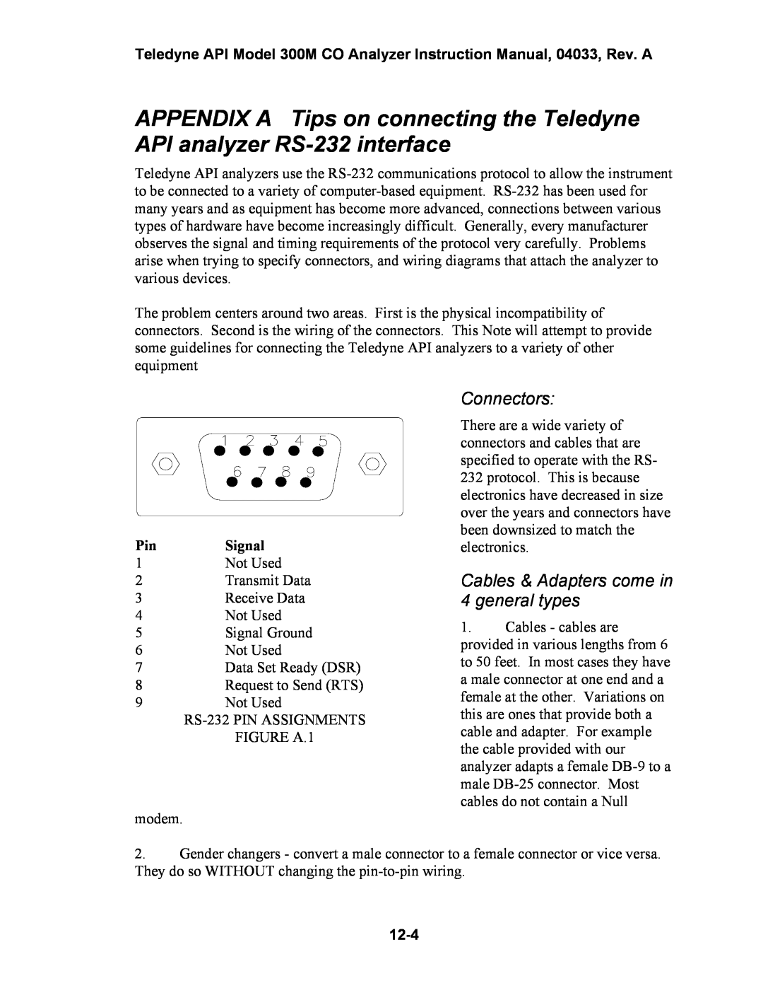
Pin | Signal |
1 | Not Used |
2 | Transmit Data |
3 | Receive Data |
4 | Not Used |
5 | Signal Ground |
6 | Not Used |
7 | Data Set Ready (DSR) |
8 | Request to Send (RTS) |
9 | Not Used |
| |
| FIGURE A.1 |
modem.
Connectors:
There are a wide variety of connectors and cables that are specified to operate with the RS- 232 protocol. This is because electronics have decreased in size over the years and connectors have been downsized to match the electronics.
Cables & Adapters come in 4 general types
1.Cables - cables are provided in various lengths from 6 to 50 feet. In most cases they have a male connector at one end and a female at the other. Variations on this are ones that provide both a cable and adapter. For example the cable provided with our analyzer adapts a female
2.Gender changers - convert a male connector to a female connector or vice versa. They do so WITHOUT changing the
