Teledyne API Model 300M CO Analyzer Instruction Manual, 04033, Rev. A
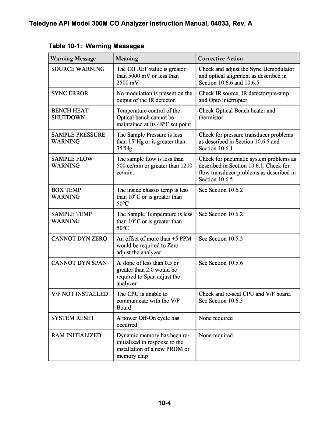
Table 10-1: Warning Messages
Warning Message | Meaning | Corrective Action |
SOURCE WARNING | The CO REF value is greater | Check and adjust the Sync Demodulator |
| than 5000 mV or less than | and optical alignment as described in |
| 2500 mV | Section 10.6.6 and 10.6.5 |
|
|
|
SYNC ERROR | No modulation is present on the | Check IR source, IR |
| output of the IR detector. | and Opto interrupter |
|
|
|
BENCH HEAT | Temperature control of the | Check Optical Bench heater and |
SHUTDOWN | Optical bench cannot be | thermistor |
| maintained at its 48°C set point |
|
|
|
|
SAMPLE PRESSURE | The Sample Pressure is less | Check for pressure transducer problems |
WARNING | than 15"Hg or is greater than | as described in Section 10.6.5 and |
| 35"Hg | Section 10.6.1 |
|
|
|
SAMPLE FLOW | The sample flow is less than | Check for pneumatic system problems as |
WARNING | 500 cc/min or greater than 1200 | described in Section 10.6.1. Check for |
| cc/min. | flow transducer problems as described in |
|
| Section 10.6.5 |
|
|
|
BOX TEMP | The inside chassis temp is less | See Section 10.6.2 |
WARNING | than 10°C or is greater than |
|
| 50°C |
|
|
|
|
SAMPLE TEMP | The Sample Temperature is less | See Section 10.6.2 |
WARNING | than 10°C or is greater than |
|
| 50°C |
|
|
|
|
CANNOT DYN ZERO | An offset of more than ±5 PPM | See Section 10.5.5 |
| would be required to Zero |
|
| adjust the analyzer |
|
CANNOT DYN SPAN | A slope of less than 0.5 or | See Section 10.5.6 |
| greater than 2.0 would be |
|
| required to Span adjust the |
|
| analyzer |
|
|
|
|
V/F NOT INSTALLED | The CPU is unable to | Check and |
| communicate with the V/F | See Section 10.6.3 |
| Board |
|
|
|
|
SYSTEM RESET | A power | None required |
| occurred |
|
|
|
|
RAM INITIALIZED | Dynamic memory has been re- | None required |
| initialized in response to the |
|
| installation of a new PROM or |
|
| memory chip |
|
|
|
|
