Teledyne API Model 300M CO Analyzer Instruction Manual, 04033, Rev. A
5.2.1 Signal I/O
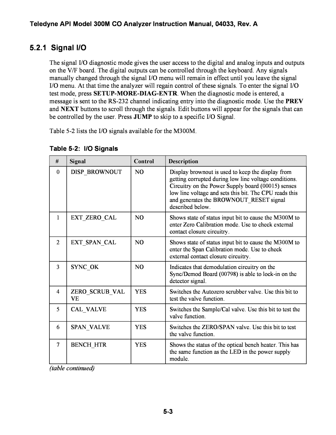
The signal I/O diagnostic mode gives the user access to the digital and analog inputs and outputs on the V/F board. The digital outputs can be controlled through the keyboard. Any signals manually changed through the signal I/O menu will remain in effect until you leave the signal I/O menu. At that time the analyzer will regain control of these signals. To enter the signal I/O test mode, press
Table
Table 5-2: I/O Signals
# | Signal | Control | Description |
0 | DISP_BROWNOUT | NO | Display brownout is used to keep the display from |
|
|
| getting corrupted during low line voltage conditions. |
|
|
| Circuitry on the Power Supply board (00015) senses |
|
|
| low line voltage and sets this bit. The CPU reads this |
|
|
| and generates the BROWNOUT_RESET signal |
|
|
| described below. |
|
|
|
|
1 | EXT_ZERO_CAL | NO | Shows state of status input bit to cause the M300M to |
|
|
| enter Zero Calibration mode. Use to check external |
|
|
| contact closure circuitry. |
|
|
|
|
2 | EXT_SPAN_CAL | NO | Shows state of status input bit to cause the M300M to |
|
|
| enter the Span Calibration mode. Use to check |
|
|
| external contact closure circuitry. |
|
|
|
|
3 | SYNC_OK | NO | Indicates that demodulation circuitry on the |
|
|
| Sync/Demod Board (00798) is able to |
|
|
| detector signal. |
|
|
|
|
4 | ZERO_SCRUB_VAL | YES | Switches the Autozero scrubber valve. Use this bit to |
| VE |
| test the valve function. |
|
|
|
|
5 | CAL_VALVE | YES | Switches the Sample/Cal valve. Use this bit to test the |
|
|
| valve function. |
|
|
|
|
6 | SPAN_VALVE | YES | Switches the ZERO/SPAN valve. Use this bit to test |
|
|
| the valve function. |
|
|
|
|
7 | BENCH_HTR | YES | Shows the status of the optical bench heater. This has |
|
|
| the same function as the LED in the power supply |
|
|
| module. |
|
|
|
|