Teledyne API Model 300M CO Analyzer Instruction Manual, 04033, Rev. A
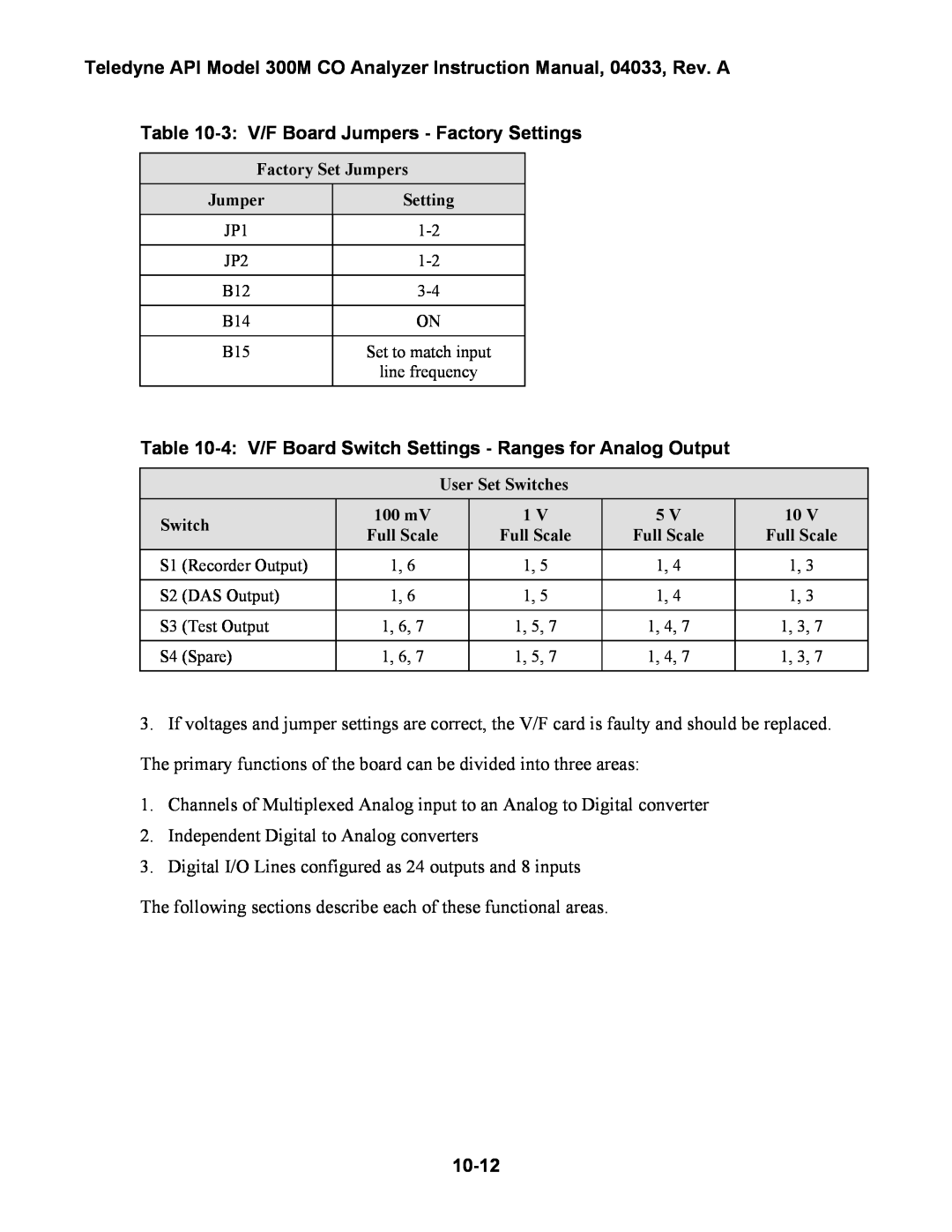
Table 10-3: V/F Board Jumpers - Factory Settings
Factory Set Jumpers
Jumper | Setting |
JP1 | |
|
|
JP2 | |
|
|
B12 | |
|
|
B14 | ON |
|
|
B15 | Set to match input |
| line frequency |
|
|
Table
User Set Switches
Switch | 100 mV | 1 V | 5 V | 10 V | ||
Full Scale | Full Scale | Full Scale | Full Scale | |||
|
| |||||
S1 | (Recorder Output) | 1, 6 | 1, 5 | 1, 4 | 1, 3 | |
|
|
|
|
|
| |
S2 | (DAS Output) | 1, 6 | 1, 5 | 1, 4 | 1, 3 | |
|
|
|
|
|
| |
S3 | (Test Output | 1, 6, 7 | 1, 5, 7 | 1, 4, 7 | 1, 3, 7 | |
|
|
|
|
|
| |
S4 | (Spare) | 1, 6, 7 | 1, 5, 7 | 1, 4, 7 | 1, 3, 7 | |
|
|
|
|
|
| |
3.If voltages and jumper settings are correct, the V/F card is faulty and should be replaced. The primary functions of the board can be divided into three areas:
1.Channels of Multiplexed Analog input to an Analog to Digital converter
2.Independent Digital to Analog converters
3.Digital I/O Lines configured as 24 outputs and 8 inputs
The following sections describe each of these functional areas.