Teledyne API Model 300M CO Analyzer Instruction Manual, 04033, Rev. A
Table
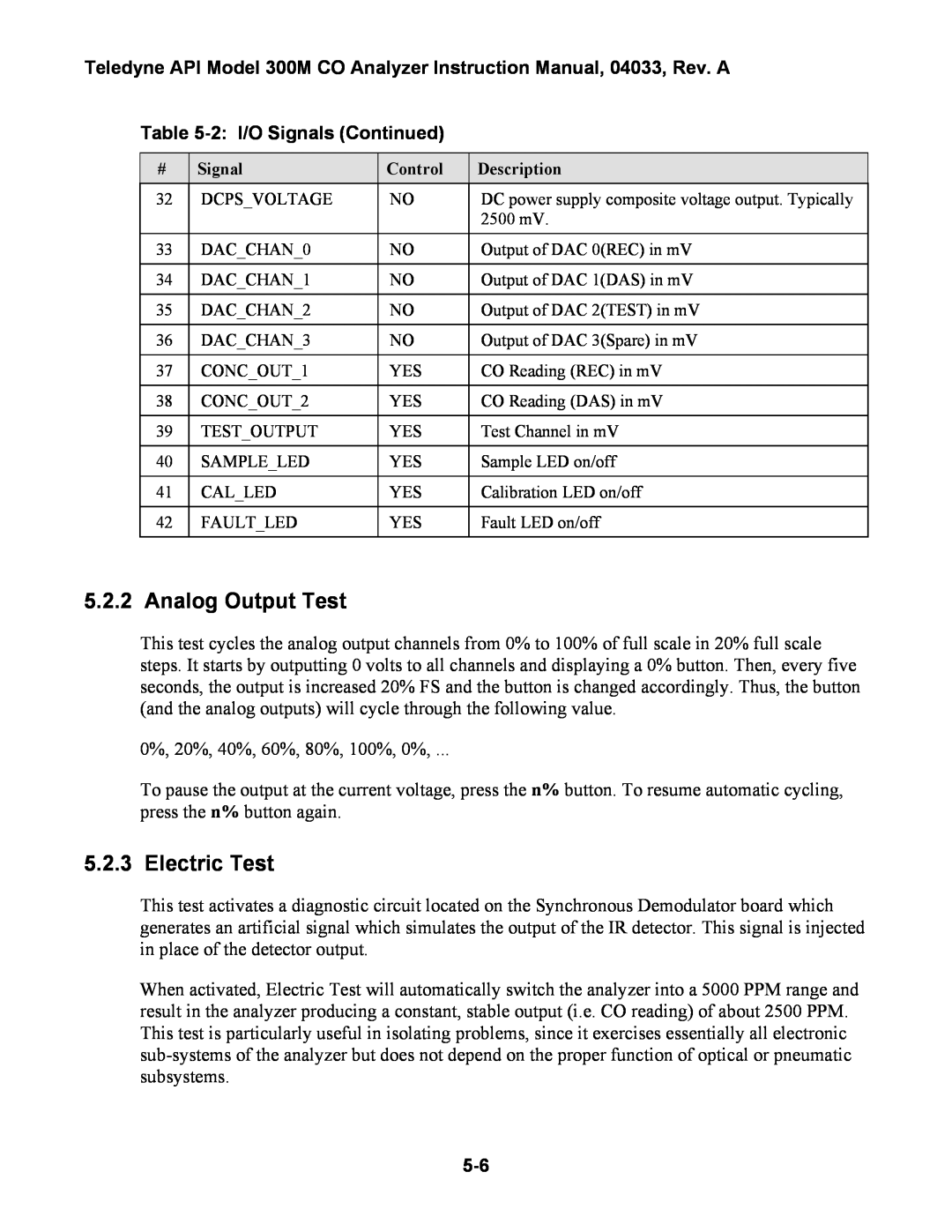
# | Signal | Control | Description |
32 | DCPS_VOLTAGE | NO | DC power supply composite voltage output. Typically |
|
|
| 2500 mV. |
|
|
|
|
33 | DAC_CHAN_0 | NO | Output of DAC 0(REC) in mV |
|
|
|
|
34 | DAC_CHAN_1 | NO | Output of DAC 1(DAS) in mV |
|
|
|
|
35 | DAC_CHAN_2 | NO | Output of DAC 2(TEST) in mV |
|
|
|
|
36 | DAC_CHAN_3 | NO | Output of DAC 3(Spare) in mV |
|
|
|
|
37 | CONC_OUT_1 | YES | CO Reading (REC) in mV |
|
|
|
|
38 | CONC_OUT_2 | YES | CO Reading (DAS) in mV |
|
|
|
|
39 | TEST_OUTPUT | YES | Test Channel in mV |
|
|
|
|
40 | SAMPLE_LED | YES | Sample LED on/off |
|
|
|
|
41 | CAL_LED | YES | Calibration LED on/off |
|
|
|
|
42 | FAULT_LED | YES | Fault LED on/off |
|
|
|
|
5.2.2 Analog Output Test
This test cycles the analog output channels from 0% to 100% of full scale in 20% full scale steps. It starts by outputting 0 volts to all channels and displaying a 0% button. Then, every five seconds, the output is increased 20% FS and the button is changed accordingly. Thus, the button (and the analog outputs) will cycle through the following value.
0%, 20%, 40%, 60%, 80%, 100%, 0%, ...
To pause the output at the current voltage, press the n% button. To resume automatic cycling, press the n% button again.
5.2.3 Electric Test
This test activates a diagnostic circuit located on the Synchronous Demodulator board which generates an artificial signal which simulates the output of the IR detector. This signal is injected in place of the detector output.
When activated, Electric Test will automatically switch the analyzer into a 5000 PPM range and result in the analyzer producing a constant, stable output (i.e. CO reading) of about 2500 PPM. This test is particularly useful in isolating problems, since it exercises essentially all electronic