AIR-CONDITIONER
Contents
New Refrigerant Air Conditioner Installation
For general public use
For Reference
Specifications
Specifications
RAS-10SKVP-ND RAS-13SKVP-ND RAS-16SKVP-ND
Cooling
Operation Characteristic Curve
Heating
Current
Heating
Capacity Variation Ratio According to Temperature
Cooling
Capacity ratio % 110 100
Piping Materials and Joints Used
Safety During Installation/Servicing
Refrigerant Piping Installation
Copper Pipes
Joints
Flare processing procedures and precautions
Processing of Piping Materials
Flare tool for R22 Conventional flare tool
Flare tool for R410A Conventional flare tool
Clutch type Wing nut type
Diameter
Wrenches available on the market
Flare Connecting Procedures and Precautions
Nm kgfcm
General tools Conventional tools can be used
Tools
Required Tools
1 Configuration of refrigerant charging
Recharging of Refrigerant
Flux
Brazing of Pipes
Materials for Brazing
Brazing
Never use gas other than Nitrogen gas
Construction Views
Indoor Unit
WH-H05JE
Detailed a leg part
Mounting dimensions of anchor bolt
Outdoor Unit
Detailed B leg part
Board
MCC-5009
MCC-5045
RAS-10SAVP-ND, RAS-13SAVP-ND, RAS-16SAVP-ND
Parts name Model name Rating
Parts name Type Specifications
MP24Z3N
CAM-MD12TF DC12V
Refrigerant Cycle Diagram
CAM-B22YGTF-3
Operation Data Cooling
AUTO, COOL, DRY, Heat
Operation START/STOP Operation Mode Selection
Sleep Mode
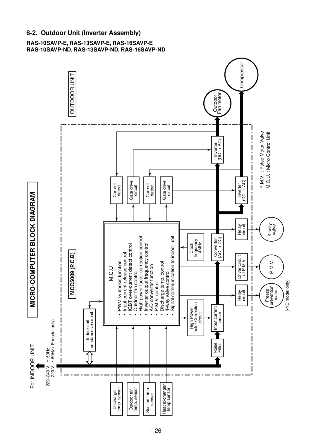
MCC5009 P.C.B
Outdoor Unit Inverter Assembly
For Indoor Unit
Role of outdoor unit controller
Outline of Air Conditioner Control
Role of indoor unit controller
Operations followed to
Operation Description
Filter Indicator
Remote Controller and Its Fuctions
Auto Restart Function
Outdoor unit
Remote controller
Indoor unit
ON/OFF
Auto operation
DRY operation
Indoor fan air flow rate
Symbols
Indication Fan speed
Indication Fan speed
Operation flow and applicable data, etc Description
Heating operation
Cold draft preventive control
Outdoor fan shown
Outdoor temperature To
Mode, by the conditions
Table is selected
Remote controller Indoor unit
Compressor speed so that temperature of the heat
When temperature of the indoor
Exchanger detects evaporation temperature and controls
Exchanger detects condensation temperature
Condition
Operation flow and applicable data, etc
Case of operation stop
Defrost operation
Louver position in dry operation
Louver position in cooling operation
Louver position in heating operation
Air direction
Cooling operation
Sleep
Mode
Push Reset button again
When keeping Reset button pushed for
If the filter lamp goes on, push Reset
Temporary
Purpose
Operation
Setup value Power OFF
SH control Release control PMV open degree control Stop by
Clean operation
This completes the clean operation setting
Setting the clean operation cancel
Setting the clean operation
Indoor P.C. board
Setting the remote controller
Setting the unit
8C Heat operation -ND model only
Indoor control P.C. board At shipment Purpose
Heat operation
With Quiet control/Non-select method Purpose
To reduce noise, Reset button
Outdoor
During operation of air conditioner
Start
During stop of air conditioner
On 8˚C Heat
Auto TSC
Basic fan control
Indoor fan control
Compressor speed control Refer to 4. Capacity control
OFF
Base plate cord heater control Purpose
To temp Heater output Operation
When the unit is in operation
How to Set the Auto Restart Function
When the unit is standby Not operating
When the system is on stand-by not operating
Power Failure During Timer Operation
How to Turn Off Filter Indicator
When the system is operating
Parts Name of Remote Controller
Display
Automatic operation
Do not allow the drain hose to become slack
Safety Cautions
For the rear left and left piping
Accessory and Installation Parts
Optional Parts, Accessories and Tools
Optional Installation Parts
Changes in the product and components
Installation/Servicing Tools
New tools for R410A
New tools for R410A Applicable to R22 model Changes
Drilling and Mounting Installation Plate
Installation Location
Remote controller
Mounting the installation plate
Electrical Work
When the installation plate is directly mounted on the wall
Wiring Connection How to connect the connecting cable
Anchor bolt Projection 15mm or less
Die-cutting front panel slit
How to remove the drain cap
How to remove the drain hose
Changing drain hose
Case of bottom right or bottom left piping
How to attach the drain cap
How to attach the drain hose
Left-hand connection with piping
Shield pipe Drain hose Inside the room
Indoor Unit Installation
Drainage
Precautions for adding refrigerant
Strong wind
Projection margin in flaring a Unit mm
Draining the Water
Refrigerant Piping Connection Flaring
Flaring size B Unit mm
To secure To tighten
Tightening Connection
Use a vacuum pump
Stripping length of connecting cable
Packed Valve handling precautions
Wiring Connection
Model RAS
Test Operation
Control circuitry has an uninsulated construction
Precautions when handling the new inverter 3DV Inverter
Troubleshooting Procedure
JAVP-E series insulated type
Sensor leads
Do not lay the circuit board assembly flat
Discharging method
Inverter cover
First Confirmation
Confirmation of Power Supply
Confirmation of Power Voltage
Operation Which is not a Trouble Program Operation
Which lamp does flash?
Primary Judgment
Judgment by Flashing LED of Indoor Unit
Check Block display Description for self-diagnosis Code
Push START/STOP button to release the service mode
Self-Diagnosis by Remote Controller Check Code
How to Use Remote Controller in Service Mode
Push on or OFF button
Air Block Cause of operation
Block distinction
Judgment and action
Remarks
Block Cause of operation
Confirmation procedure
Judgment of Trouble by Every Symptom
Indoor Unit Including Remote Controller
Primary check
Only the indoor motor fan does not operate
Inspection procedure
Cause
Troubleshooting for remote controller
Outdoor unit does not operate
Wiring Failure Interconnecting and Serial Signal Wire
Check procedure Select phenomena described below
Terminal block at indoor side
1C1E
Check Code 1C Miswiring in indoor/outdoor units and 1E
Check procedure
Conduction check of micro-switch
Troubleshooting
How to Check Whether the Air Purifier is Good or Not
Primary check
Diagnosis/Process flowchart Contents Summary
How to Diagnose Trouble in Outdoor Unit
Summarized Inner Diagnosis of Inverter Assembly
Operating precautions
How to Check Simply the Main Parts
How to Check the P.C. Board Indoor Unit
Inspection procedures
OPERATION, TIMER, Filter
Check procedures
Procedure Check points Causes
Cool
Sensor characteristic table
11-9-2. P.C. Board Layout
Outdoor Unit
Part name Checking procedure
Indoor Unit Other Parts
Tester rod Resistance value Good product
Checking Method for Each Part
Case that product is good
Symptom
Cause
Part name Procedures Remarks
12-1 Indoor Unit
How to assemble the front panel
How to assemble the high voltage generator
How to assemble the electric parts box
Slide the horizontal
Remove the two screws used to secure Bearing base
Pull out here
Drain pipe
Board layout
Part name Procedure Remarks
Microcomputer
No. Part name Procedure Remarks Common 1. Detachment
Attachment
No. Part name Procedure Remarks
STIT-4X8MSZN
100
Some cases
101
Disconnect the leads and connectors connected to
Other parts from the control board assembly
Board base
102
Side cabinet left
103
Detachment
Handling precaution
104
Detail B
105
Detail a Arrow D Detail C
Detail a Arrow D
Part name
106
Parts name Qty Remarks
MCC-5009-04
107
MCC-5009
108
240
237
Part Description
402 407, 408 403 406 404 405 410401
109
110
402 411, 412 403 406 404 405 410401
111
13, 16, 19 14, 15, 17 20, 21, 23, 24
112
113
13, 16, 19 14, 15, 17 20, 21, 23, 24 CORD, HEATER, Ass’y
114
115
13-3. P.C. Board Layout
116
117
Model
118
Corresponding
Toshiba Carrier Corporation