|
| E6581090 |
|
| Loads that generate negative torque |
|
| When combined with loads that generate negative torque the protection for overvoltage and |
|
| overcurrent on the inverter will go into operation and may cause a trip. For this kind of situation, |
|
| you must install a dynamic braking resistor, etc. that complies with the load conditions. |
|
|
|
1 |
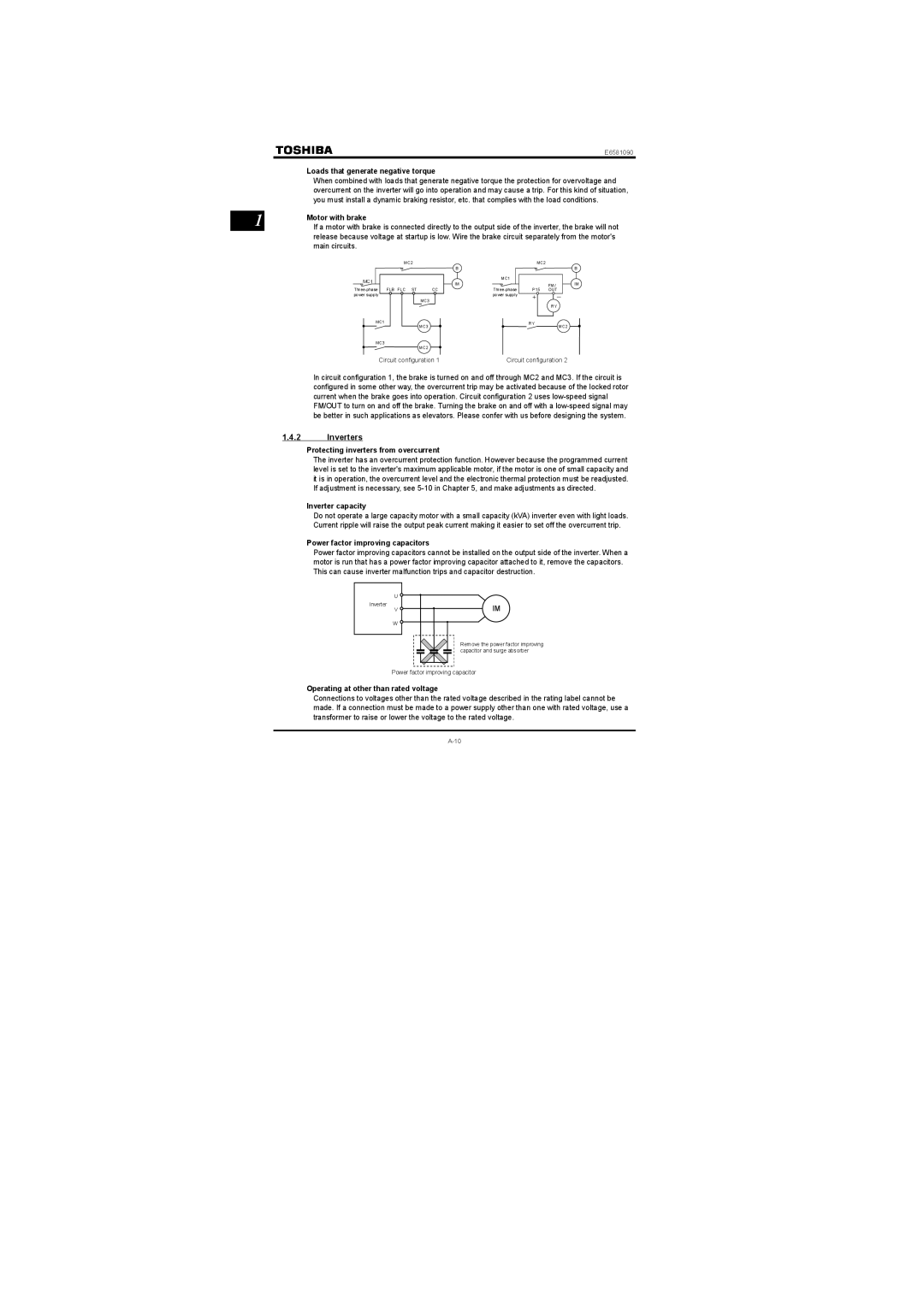
| Motor with brake |
| If a motor with brake is connected directly to the output side of the inverter, the brake will not |
release because voltage at startup is low. Wire the brake circuit separately from the motor's main circuits.
MC2 |
|
MC1 |
|
CC | |
power supply |
|
| MC3 |
MC1 | MC3 |
| |
MC3 | MC2 |
|
B
MC1
IM
MC2
| B |
FM/ | IM |
P15 OUT
+―
RY
RYMC2
Circuit configuration 1
Circuit configuration 2
In circuit configuration 1, the brake is turned on and off through MC2 and MC3. If the circuit is configured in some other way, the overcurrent trip may be activated because of the locked rotor current when the brake goes into operation. Circuit configuration 2 uses
1.4.2Inverters
Protecting inverters from overcurrent
The inverter has an overcurrent protection function. However because the programmed current level is set to the inverter's maximum applicable motor, if the motor is one of small capacity and it is in operation, the overcurrent level and the electronic thermal protection must be readjusted. If adjustment is necessary, see
Inverter capacity
Do not operate a large capacity motor with a small capacity (kVA) inverter even with light loads. Current ripple will raise the output peak current making it easier to set off the overcurrent trip.
Power factor improving capacitors
Power factor improving capacitors cannot be installed on the output side of the inverter. When a motor is run that has a power factor improving capacitor attached to it, remove the capacitors. This can cause inverter malfunction trips and capacitor destruction.
U ![]()
Inverter
V ![]()
W ![]()
IM
Remove the power factor improving capacitor and surge absorber
Power factor improving capacitor
Operating at other than rated voltage
Connections to voltages other than the rated voltage described in the rating label cannot be made. If a connection must be made to a power supply other than one with rated voltage, use a transformer to raise or lower the voltage to the rated voltage.