|
|
|
|
| E6581090 | |
Termina | Input/ | Function | Specifications | Inverter internal circuit | ||
l symbol | output | |||||
|
|
|
| |||
|
| Multifunction programmable |
|
|
| |
|
| output. |
|
| +15V | |
|
| Standard default setting: |
|
|
| |
|
| output frequency. | 1mA |
|
| |
|
| Meters connectable to | DC ammeter or 7.5Vdc |
|
| |
FM/ |
| FM/OUT: 1mAdc | (10Vdc) |
| +15V | |
|
|
| ||||
Output | ammeter or 7.5Vdc (10Vdc) | DC voltmeter |
|
| ||
OUT | 3.4K |
| ||||
|
|
|
| |||
|
|
| FM/OUT◎ |
| ||
|
| (PWM output). | Open collector output: |
| ||
|
|
| 47 | |||
|
| Possible to switch to |
|
| ||
|
| programmable open collector |
|
|
| |
|
| output by changing a |
|
|
| |
|
| parameter. |
|
|
| |
|
|
|
|
| +15V | |
|
| 15Vdc power output. |
|
|
| |
P15 | Output ※For more on how to use, see | P15◎ |
| |||
|
| 6.1.1 and 6.2.6. |
|
|
| |
|
| Multifunction programmable |
| FLA ◎ | +15V | |
|
| relay contact output. Contact |
| |||
|
|
|
| |||
|
|
|
|
| ||
|
| ratings: 250Vac - 2A (cosφ=1), |
|
| ||
FLA |
| 30Vdc - 1A, 250Vac - 1A | FLB ◎ |
| ||
| (cosφ=0.4). Standard default | (cosφ=1): |
| FL | ||
FLB | Output | setting: Monitoring of status of | at resistance load | FLC ◎ |
| |
FLC |
| inverter’s protection function. |
| 100 | ||
|
| Activation of the protection |
|
| ||
|
| function causes circuit |
|
|
| |
|
|
|
|
| ||
|
|
|
|
| ||
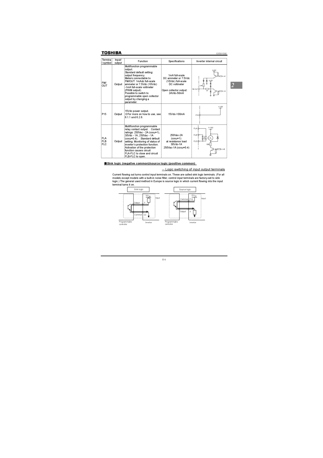
■Sink logic (negative common)/source logic (positive common)
⋅⋅⋅Logic switching of input output terminals
Current flowing out turns control input terminals on. These are called sink logic terminals. (For all models except models with a
Sink logic |
| Source logic |
| |
| 15VDC |
| 15VDC |
|
| Input | Common | P15 | Input |
|
|
| ||
Output | F |
|
|
|
|
| Output | F |
|
Common CC |
|
|
| |
Programmable | Inverter | Programmable | Inverter |
|
controller | controller |
| ||
|
|
| ||
2