E6581090
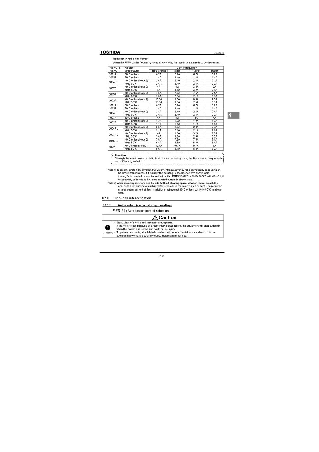
Reduction in rated load current
When the PWM carrier frequency is set above 4kHz, the rated current needs to be decreased.
VFNC1S- | Ambient |
| Carrier frequency |
|
|
| ||
VFNC1- | temperature | 4kHz or less | 8kHz | 12kHz | 16kHz |
|
| |
2001P | 50°C or less | 0.7A | 0.7A | 0.7A | 0.7A |
|
| |
2002P | 50°C or less | 1.4A | 1.4A | 1.4A | 1.4A |
|
| |
2004P | 40°C or less Note 2) | 2.4A | 2.4A | 2.4A | 2.4A |
|
| |
40 to 50°C | 2.4A | 2.4A | 2.4A | 2.2A |
|
| ||
|
|
| ||||||
2007P | 40°C or less Note 2) | 4A | 4A | 3.6A | 3A |
|
| |
40 to 50°C | 4A | 3.6A | 3.2A | 2.8A |
|
| ||
|
|
| ||||||
2015P | 40°C or less Note 2) | 7.5A | 7.5A | 7.5A | 7.1A |
|
| |
40 to 50°C | 7.5A | 7.5A | 7.1A | 6.3A |
|
| ||
|
|
| ||||||
2022P | 40°C or less Note 2) | 10.0A | 9.5A | 8.5A | 7.5A |
|
| |
40 to 50°C | 10.0A | 8.5A | 7.5A | 6.5A |
|
| ||
|
|
| ||||||
1001P | 50°C or less | 0.7A | 0.7A | 0.7A | 0.7A |
|
| |
1002P | 50°C or less | 1.4A | 1.4A | 1.4A | 1.4A |
|
| |
| 40°C or less Note 2) | 2.4A | 2.4A | 2.4A | 2.4A |
|
| |
1004P | 6 | |||||||
40 to 50°C | 2.4A | 2.4A | 2.4A | 2.2A |
| |||
|
| |||||||
1007P | 50°C or less | 4A | 4A | 4A | 4A |
| ||
| ||||||||
2002PL | 40°C or less Note 2) | 1.2A | 1.2A | 1.2A | 1.2A |
|
| |
40 to 50°C | 1.1A | 1.1A | 1.1A | 1.1A |
|
| ||
|
|
| ||||||
2004PL | 40°C or less Note 2) | 2.3A | 2.3A | 2.3A | 2.3A |
|
| |
40 to 50°C | 2.1A | 2.1A | 2.1A | 2.1A |
|
| ||
|
|
| ||||||
2007PL | 40°C or less Note 2) | 4A | 3.6A | 3.2A | 2.8A |
|
| |
40 to 50°C | 3.6A | 3.2A | 2.9A | 2.5A |
|
| ||
|
|
| ||||||
2015PL | 40°C or less Note 2) | 7.5A | 7.5A | 7.5A | 7.1A |
|
| |
40 to 50°C | 6.8A | 6.8A | 6.8A | 6.4A |
|
| ||
|
|
| ||||||
2022PL | 40°C or less Note2) | 10.7A | 10.1A | 9.1A | 8A |
|
| |
40 to 50°C | 9.6A | 9.1A | 8.2A | 7.2A |
|
| ||
|
|
| ||||||
 • Function
Although the rated current at 4kHz is shown on the rating plate, the PWM carrier frequency is ![]() set to 12kHz by default.
set to 12kHz by default.![]()
Note 1) In order to protect the inverter, PWM carrier frequency may fall automatically depending on
the circumstances even if it is under the derating in accordance with above table.
If using
Note 2) When installing inverters side by side (without allowing space between them), detach the label on the top surface of each inverter, and reduce the rated output current. The reduction in rated output current at this installation must use not 40°C or less but 40 to 50°C in above table.
6.10Trip-less intensification
6.10.1
:
![]() Caution
Caution
•Stand clear of motors and mechanical equipment.
If the motor stops because of a momentary power failure, the equipment will start suddenly when the power is restored, and could cause injury.
Mandatory • To prevent accidents, attach labels caution that there is the risk of a sudden start in the event of a power failure to all inverters, motors and machines.