E6581090
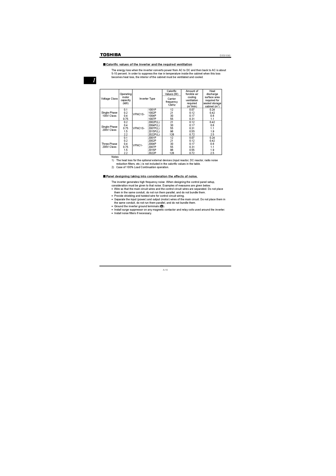
■Calorific values of the inverter and the required ventilation
1
The energy loss when the inverter converts power from AC to DC and then back to AC is about
|
|
|
| Calorific | Amount of | Heat | |
| Operating |
|
| Values (W) | forcible air | discharge | |
Voltage Class | motor | Inverter Type | Carrier | cooling | surface area | ||
capacity | ventilation | required for | |||||
|
|
| frequency | ||||
| (kW) |
|
| required | sealed storage | ||
|
|
| 12kHz | ||||
|
|
|
| (m3/min) | cabinet (m2) | ||
0.1 |
| 1001P | 12 | 0.07 | 0.24 | ||
0.2 | VFNC1S- | 1002P | 21 | 0.12 | 0.42 | ||
100V Class | 0.4 | 1004P | 30 | 0.17 | 0.6 | ||
| |||||||
| 0.75 |
| 1007P | 55 | 0.31 | 1.1 | |
| 0.2 |
| 2002P(L) | 21 | 0.12 | 0.42 | |
0.4 |
| 2004P(L) | 30 | 0.17 | 0.6 | ||
0.75 | VFNC1S- 2007P(L) | 55 | 0.31 | 1.1 | |||
200V Class | |||||||
1.5 |
| 2015P(L) | 96 | 0.55 | 1.9 | ||
|
| ||||||
| 2.2 |
| 2022P(L) | 126 | 0.72 | 2.5 | |
| 0.1 |
| 2001P | 12 | 0.07 | 0.24 | |
| 0.2 |
| 2002P | 21 | 0.12 | 0.42 | |
0.4 | VFNC1- | 2004P | 30 | 0.17 | 0.6 | ||
200V Class | 0.75 | 2007P | 55 | 0.31 | 1.1 | ||
| |||||||
| 1.5 |
| 2015P | 96 | 0.55 | 1.9 | |
| 2.2 |
| 2022P | 126 | 0.72 | 2.5 | |
Notes
1)The heat loss for the optional external devices (input reactor, DC reactor, radio noise reduction filters, etc.) is not included in the calorific values in the table.
2)Case of 100% Load Continuation operation.
■Panel designing taking into consideration the effects of noise.
The inverter generates high frequency noise. When designing the control panel setup, consideration must be given to that noise. Examples of measures are given below.
•Wire so that the main circuit wires and the control circuit wires are separated. Do not place them in the same conduit, do not run them parallel, and do not bundle them.
•Provide shielding and twisted wire for control circuit wiring.
•Separate the input (power) and output (motor) wires of the main circuit. Do not place them in the same conduit, do not run them parallel, and do not bundle them.
•Ground the inverter ground terminals (![]() ).
).
•Install surge suppressor on any magnetic contactor and relay coils used around the inverter.
•Install noise filters if necessary.