E6581090
■How to install
|
| Warning |
| • | Do not install and operate the inverter if it is damaged or any component is |
|
| missing. |
Prohibited |
| This can result in electric shock or fire. Please consult your local agency for |
| repairs. | |
| • | Must be installed in nonflammables such as metals. |
|
| The rear panel gets very hot so that if installation is in an inflammable object, this |
Mandatory | • | can result in fire. |
Do not operate with the front panel cover removed. This can result in electric | ||
| • | shock. |
| An emergency stop device must be installed that fits with system specifications | |
|
| (e.g. cuts off input power then engages mechanical brakes). |
|
| Operation cannot be stopped immediately by the inverter alone, thus risking an |
| • | accident or injury. |
| All options used must be those specified by Toshiba. The use of any other option | |
|
| may result in an accident. |
|
| Caution |
| • | The main unit must be installed on a base that can bear the unit's weight. |
|
| If the unit is installed on a base that cannot withstand that weight, the unit may fall |
Mandatory | • | resulting in injury. |
If braking is necessary (to hold motor shaft), install a mechanical brake. The brake | ||
|
| on the inverter will not function as a mechanical hold, and if used for that purpose, |
|
| injury may result. |
■Installation location
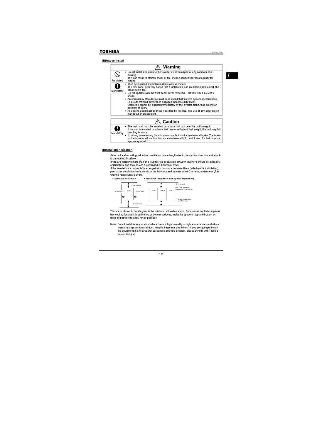
Select a location with good indoor ventilation, place lengthwise in the vertical direction and attach to a metal wall surface.
If you are installing more than one inverter, the separation between inverters should be at least 5 centimeters, and they should be arranged in horizontal rows.
If the inverters are horizontally arranged with no space between them
• Standard installation | • Horizontal installation |
1
10 cm or more
| VFnC1 |
|
5 cm or more | 5 cm or more | |
|
|
|
|
|
|
10 cm or more
VFnC1 VFnC1 VFnC1
10 cm or more
Peel of the ventilation seals on top of the inverter
Ambient temperature of 40°C or less
The space shown in the diagram is the minimum allowable space. Because air cooled equipment has cooling fans built in on the top or bottom surfaces, make the space on top and bottom as large as possible to allow for air passage.
Note: Do not install in any location where there is high humidity or high temperatures and where there are large amounts of dust, metallic fragments and oilmist. If you are going to install the equipment in any area that presents a potential problem, please consult with Toshiba before doing so.