E6581090
5. Basic parameters
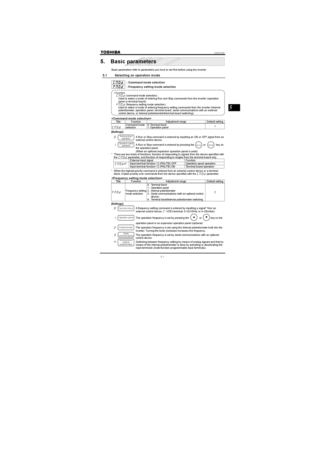
Basic parameters refer to parameters you have to set first before using the inverter.
5.1Selecting an operation mode
: Command mode selection
: Frequency setting mode selection
•Function
(command mode selection) :
Used to select a mode of entering Run and Stop commands from the inverter (operation panel or terminal board).
(frequency setting mode selection) :
Used to select a mode of entering frequency setting commands from the inverter (internal 5 potentiometer, operation panel, terminal board, serial communications with an external
control device, or internal potentiometer/terminal board switching).
<Command mode selection>
Title | Function | Adjustment range | Default setting |
| Command mode | 0: Terminal block | 1 |
| selection | 1: Operation panel |
[Settings]
: Terminal block operation
: Operation panel operation
A Run or Stop command is entered by inputting an ON or OFF signal from an external control device.
A Run or Stop command is entered by pressing the RUN or STOP key on the operation panel.
(When an optional expansion operation panel is used)
* There are two kinds of functions: function of responding to signals from the device specified with the parameter, and function of responding to singles from the terminal board only.
| External input signal |
| Function |
=1 | Input terminal function 12 | (PNL/TB) OFF | Operation panel operation |
| Input terminal function 12 | (PNL/TB) ON | Terminal board operation |
* When the
<Frequency setting mode selection>
Title | Function |
| Adjustment range | Default setting |
|
| 0 | : Terminal block |
|
|
| 1 | : Operation panel |
|
| Frequency setting | 2 | : Internal potentiometer | 2 |
| mode selection | 3 | : Serial communications (with an optional control |
|
|
|
| device) |
|
|
| 4 | : Terminal block/internal potentiometer switching |
|
[Settings]
: Terminal外部信block号 A frequency setting command is entered by inputting a signal* from an external control device. (*: VI/S3 terminal: 0~(5)10Vdc or 4~20mAdc)
: Operation panel
: Potentiometer
: Serial communications
Terminal block/
: internal potentiometer
The operation frequency is set by pressing the | ▲ | or | ▼ | key on the |
|
|
operation panel or an expansion operation panel (optional).
The operation frequency is set using the internal potentiometer built into the inverter. Turning the knob clockwise increases the frequency.
The operation frequency is set by serial communications with an optional control device.
Switching between frequency setting by means of analog signals and that by means of the internal potentiometer is done by activating or deactivating the input terminals