Manuals
/
Xantrex Technology
/
Lawn and Garden
/
Portable Generator
Xantrex Technology
4 XW Auto Generator Start Basic Menu Contents, The XW Auto Gen Start Menu
Models:
XW
1
55
124
124
Download
124 pages
55.26 Kb
52
53
54
55
56
57
58
59
<
>
Troubleshooting
Specs
Install
2 Starting and Stopping the Generator- - - - - - - - - - - - - - - - - - - - - - - - - - - 4-3 -3 Using the Quiet Time Feature - - - - - - - - - - - - - - - - - - - - - - - - - - - - - - - 4-4 -4 Changing the Mode to Standby - - - - - - - - - - - - - - - - - - - - - - - - - - - - - - 4-6 -5 Returning the Mode to Operating- - - - - - - - - - - - - - - - - - - - - - - - - - - - - 4-7 Figure A-1 XW Auto Generator Start Dimensions - - - - - - - - - - - - - - - - - - - - - - - - A-3 Figure C-1 RunMode Timing Diagram- - - - - - - - - - - - - - - - - - - - - - - - - - - - - - - - C-2 Figure C-2 MomentaryRun Mode Timing Diagram - - - - - - - - - - - - - - - - - - - - - - - C-3 Figure C-3 GlowStop Mode Timing Diagram - - - - - - - - - - - - - - - - - - - - - - - - - - - C-4 Figure C-4 StartStop Mode Timing Diagram - - - - - - - - - - - - - - - - - - - - - - - - - - - - C-5 Figure C-5 PulseStop Mode Timing Diagram - - - - - - - - - - - - - - - - - - - - - - - - - - - C-6 Figure C-6 PulseStop Mode Relay 1 Behavior- - - - - - - - - - - - - - - - - - - - - - - - - - - C-6
Warranty
Dimension
Configuration
Wiring to the 20-contact Connector
Return Procedure
Default
Page 55
Image 55
The XW Auto Gen Start Menu
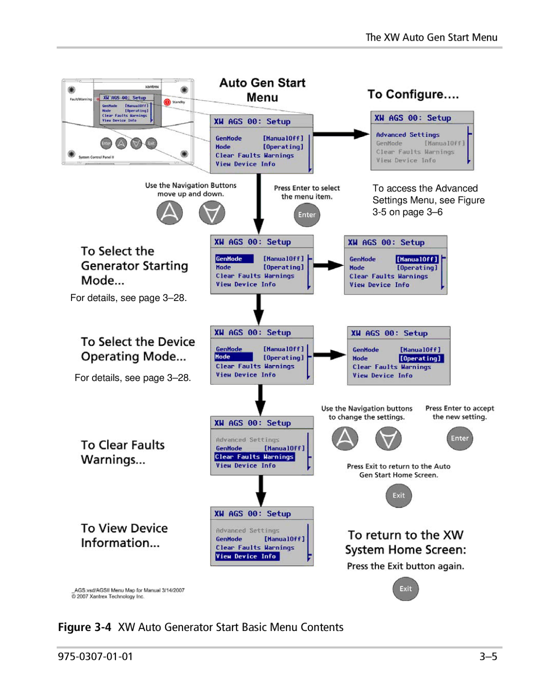
To access the Advanced Settings Menu, see Figure
3-5
on page
3–6
For details, see page
3–28.
For details, see page
3–28.
Figure
3-4
XW Auto Generator Start Basic Menu Contents
975-0307-01-01
3–5
Page 54
Page 56
Page 55
Image 55
Page 54
Page 56
Contents
Owner’s Guide
XW Automatic Generator Start
Page
XW Automatic Generator Start
Owner’s Guide
Disclaimer
About Xantrex
Trademarks
Notice of Copyright
Audience
About This Guide
Purpose
Scope
Related Information
Conventions Used
WARNING Save these instructions
Important Safety Instructions
General Precautions
WARNING Safety hazard
FCC Information to the User
Explosive Gas Precautions
WARNING Explosion hazard
2 Installation
Contents
1 Introduction
3 Configuration
4 Operation
C Relay Timing
5 Troubleshooting
A Specifications
B Generator Auto Start Requirements and Types
Figures
Figure 4-2 Starting and Stopping the Generator- - - - - - - - - - - - - - - - - - - - - - - - - - - 4-3 Figure 4-3 Using the Quiet Time Feature - - - - - - - - - - - - - - - - - - - - - - - - - - - - - - - 4-4 Figure 4-4 Changing the Mode to Standby - - - - - - - - - - - - - - - - - - - - - - - - - - - - - - 4-6 Figure 4-5 Returning the Mode to Operating- - - - - - - - - - - - - - - - - - - - - - - - - - - - - 4-7 Figure A-1 XW Auto Generator Start Dimensions - - - - - - - - - - - - - - - - - - - - - - - - A-3 Figure C-1 RunMode Timing Diagram- - - - - - - - - - - - - - - - - - - - - - - - - - - - - - - - C-2 Figure C-2 MomentaryRun Mode Timing Diagram - - - - - - - - - - - - - - - - - - - - - - - C-3 Figure C-3 GlowStop Mode Timing Diagram - - - - - - - - - - - - - - - - - - - - - - - - - - - C-4 Figure C-4 StartStop Mode Timing Diagram - - - - - - - - - - - - - - - - - - - - - - - - - - - - C-5 Figure C-5 PulseStop Mode Timing Diagram - - - - - - - - - - - - - - - - - - - - - - - - - - - C-6 Figure C-6 PulseStop Mode Relay 1 Behavior- - - - - - - - - - - - - - - - - - - - - - - - - - - C-6
Tables
975-0307-01-01
Tables
For this Topic
1 Introduction
Function
Purpose
for the XW Auto Generator Start Quiet Time and Exercise Time features
System Requirements
The XW Auto Generator Start uses Xanbus, a network communications
Functions
Front Panel
Features
“Bottom Panel” on page
CAUTION Equipment Damage
Bottom Panel
2 Installation
Tools and Materials Required
Preparing an Installation
Choosing a Location
WARNING Shock and Energy Hazards
Routing the Connections WARNING Explosion Hazard
To mount the XW Auto Generator Start
Installing the XW Automatic Generator Start
WARNING Shock Hazard
Mounting the Unit
CAUTION Shock Hazard
Wiring to the 20-contact Connector
WARNING Fire, Shock, and Energy Hazards
To install the XW Auto Generator Start using the wiring harness
Number
Contact Numbers and Functions
Wire
Wire Color
How many of these wires you connect and in which combination depends
Connecting the Generator
Generator Wires
Type 1 Connection Diagram
Type
XW AGS Harness Wires
Type
Figure 2-4 Type 2 Connection Diagram
Table 2-5 Type 2 Relay and Timing Preset Configurations
Generator Wires
5A fuse 5A fuse
Figure 2-5 Type 3 Connection Diagram
Table 2-6 Type 3 Relay and Timing Preset Configurations
Type
Type
Figure 2-6 Type 4 Connection Diagram
Table 2-7 Type 4 Relay and Timing Preset Configurations
Generator Wires
Type
Figure 2-7 Type 5 Connection Diagram
Table 2-8 Type 5 Relay and Timing Preset Configurations
GENERATOR RUN SIGNAL
Type
Figure 2-8 Type 6 Connection Diagram
Table 2-9 Type 6 Relay and Timing Preset Configurations
XW AGS Harness Wires
Type
Figure 2-9 Type 7 Connection Diagram two-wire
Type 7 Connection Diagram three-wire
Type 7 Relay and Timing Preset Configurations
Type
Figure 2-11 Type 8 Connection Diagram two-wire
Table 2-12 Type 9 Relay and Timing Preset Configurations
Figure 2-13 Type 9 Connection Diagram
Type
Table 2-13 Type 10 Relay and Timing Preset Configurations
Figure 2-14 Type 10 Connection Diagram
Type
Table 2-14 Type 11 Relay and Timing Preset Configurations
Figure 2-15 Type 11 Connection Diagram
Type
Table 2-15 Type 12Relay and Timing Preset Configurations
Figure 2-16 Type 12 Connection Diagram
Type
Table 2-16 Type 13 Relay and Timing Preset Configurations
Figure 2-17 Type 13 Connection Diagram
Type
Table 2-18 Wiring for Connecting an External Shutdown
Connecting the Thermostats optional
Connecting an External Shutdown optional
Table 2-17 Wiring for Connecting Thermostats
CAUTION Equipment Damage
Connecting an External Manual ON/OFF Switch optional
WARNING Fire and Shock Hazards
The external manual ON/OFF inputs wires 7 and 8 on the wiring harness are intended for wiring to one or more remote ON/OFF switches for starting and stopping the generator manually. Wire 7 Start and wire 8 Stop should each run to their own momentary-contact switch or push-button. The other contact on both switches common should be connected to wire 11 on the harness
Table 2-19 Wiring for Connecting an External Manual ON/OFF Switch
Connecting an External ON/OFF LED
Generator Battery
Figure 2-18 External ON/OFF Switch and LED Wiring Diagram
5K11
Installing the XW Automatic Generator Start
To connect the wiring harness to the XW Auto Generator Start
Connecting the Wiring Harness to the XW Auto Generator Start
CAUTION Equipment Damage
Connecting the XW Auto Generator Start to the Xanbus Network
A second network cable in a “daisy-chain” network layout
Figure 2-21 Verifying Power is Available
Verifying Power Is Available
3 Configuration
Enter
Overview
Exit
Enter
Accessing the XW Auto Generator Start Menu
Figure 3-2 Accessing the XW Automatic Generator Start Menu
Accessing the XW Auto Generator Start Menu
The XW Auto Gen Start Menu
975-0307-01-01
Figure 3-4 XW Auto Generator Start Basic Menu Contents
To access the Advanced Settings Menu, see Figure 3-5 on page
The XW Auto Gen Start Menu
For details on the Configuration menu options, see page
Figure 3-5 XW Auto Generator Start Configuration Menu Contents
QT En
The Configuration Menu
QT Begin
Generator Type Descriptions and Examples
QT End
Generator Type Descriptions and ExamplesContinued
Inverter Load Triggers
Cfg Trigger Menu
Charger Triggers
Thermostat Triggers
Default
Start DCV 30 sec
Values
Disabled, 4.0V to
Start DCV 15 min
Disabled
Start DCV 2 hr
Start DCV 24 hr
Stop Absorb
Stop Float
Stop
Temp2
Temp1
Load
Start Load
Stop Load
Cfg Gen Menu
1s to 90s increments of 1s
Starter Cool Down
Gen Cool Down
1s to 250s increments of 1s
Exercise Per
Max Run Time
XW System Control Panel, the generator will stop when “Max Run Time”
Exercise Dur
900AM
Exercise Time
Relay3
1200AM to 1150PM 12-hour clock
Gen Run Hold Time
Crank Delay
Crank Time
Preheat Time
Crank Retry Time
Gen Start Tries
Connections
Multi-unit Config
Dev Name
Dev Number
Automatic Mode
Restore Defaults
GenMode
Manual On Mode
The View Device Info Menu
Manual Off Mode
View Fault Log
Mode
Table 3-2 Trigger Event Descriptions
View Event Log
User
User Settings
Default
Setting
Multi-Unit Configuration
Setting
Default
Setting
3-34
Configuration
975-0307-01-01
4 Operation
Figure 4-1 XW Auto Generator Start Home Screen
Accessing the XW Auto Generator Start Home Screen
To start the generator manually
Starting and Stopping the Generator
To stop the generator manually
To enable Quiet Time
Using Quiet Time
To set the beginning of Quiet Time
To set the end of Quiet Time
Modes of Operation
Operation
Putting the XW Auto Generator Start in Standby Mode
Figure 4-4 Changing the Mode to Standby
Enter
Modes of Operation
Returning the XW Auto Generator Start to Operating Mode
Figure 4-5 Returning the Mode to Operating
Enter
975-0307-01-01
Operation
“Faults and Warnings” “Warning Messages” “Fault Messages”
5 Troubleshooting
page page page
To view a message from a fault list or warning list
Faults and Warnings
Warning Messages
To view a fault list or warning list
XW Auto Generator Start Warning Messages
Message
XW Auto Generator Start Warning MessagesContinued
Self
Number
Warning Messages
XW Auto Generator Start Warning MessagesContinued
XW Auto Generator Start Fault Messages
Fault Messages
Number
XW Auto Generator Start Fault Messages
Fault
Self
975-0307-01-01
Troubleshooting
All specifications are subject to change without notice
A Specifications
Limited to Class 2 levels 100 VA as in Chapter 2, page
Electrical Specifications
975-0307-01-01
Mechanical Specifications
Figure A-1 XW Auto Generator Start Dimensions
Mechanical Specifications
Regulatory Compliance
Environmental Specifications
and Types
Generator Auto
Start Requirements
Generator Starting Types
Recommended Features
Connection
Two Wire
Three-Wire Onan
Identification
Connection
Three-Wire Automotive
Connection
Identification
page C-2 page C-3 page C-4 page C-4 page C-5
C Relay Timing
“RunMode” “MomentaryRun Mode” “GlowStop Mode” “StartStop Mode”
“PulseStop Mode”
RunMode
Figure C-2 MomentaryRun Mode Timing Diagram
MomentaryRun Mode
StartStop Mode
GlowStop Mode
Figure C-3 GlowStop Mode Timing Diagram
Figure C-4 StartStop Mode Timing Diagram
PulseStop Mode
Figure C-6 PulseStop Mode Relay 1 Behavior
Figure C-5 PulseStop Mode Timing Diagram
Warranty
Warranty and Return Information
Proof of purchase may be in any one of the following forms
Exclusions
Return Material Authorization Policy
Disclaimer
Product
Out of Warranty Service
Return Procedure
Information About Your System
WA-6
Page
Page
Page
975-0307-01-01
Xantrex Technology Inc
1 800 670 0707 Tel toll free NA 1 360 925 5097 Tel direct
1 800 994 7828 Fax toll free NA