Installing the XW Automatic Generator Start
Type 7
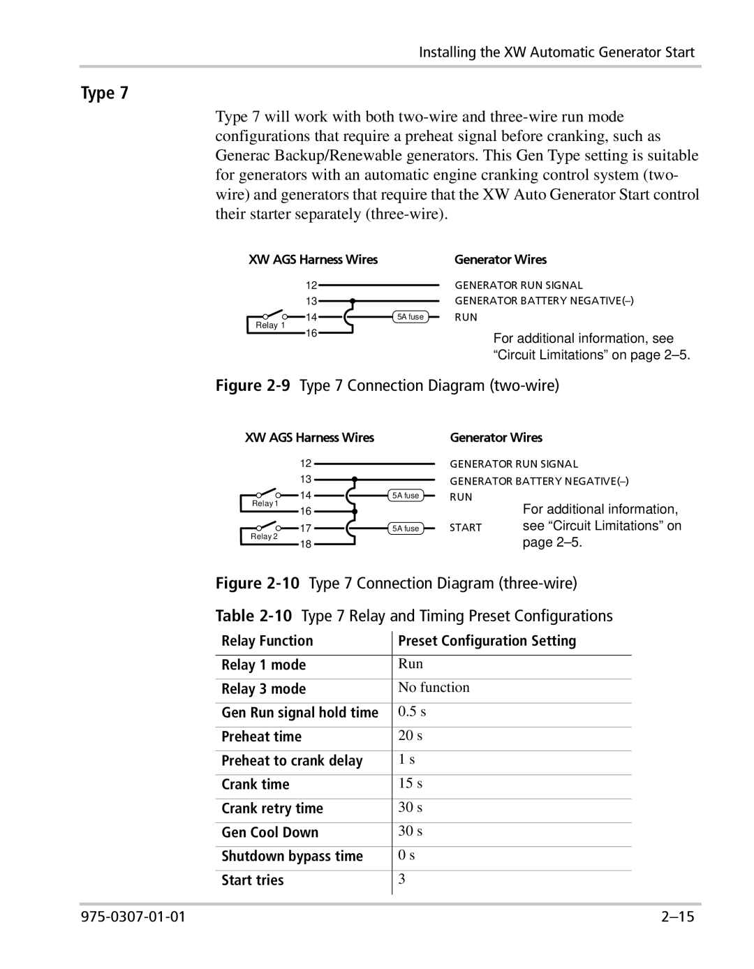
Type 7 will work with both
XW AGS Harness Wires |
| Generator Wires | ||||||
| 12 |
|
|
|
|
| GENERATOR RUN SIGNAL | |
|
|
|
|
|
| |||
| 13 |
|
|
|
|
| GENERATOR BATTERY | |
|
|
|
|
|
| |||
Relay 1 |
| 14 |
|
|
|
| 5A fuse | RUN |
|
|
|
| |||||
|
|
|
| |||||
16 |
|
|
|
|
| For additional information, see | ||
|
|
|
|
| ||||
|
|
|
|
|
| |||
“Circuit Limitations” on page 2–5.
Figure 2-9 Type 7 Connection Diagram (two-wire)
XW AGS Harness Wires
12
13
Relay 1 | 14 | 5A fuse |
16 |
| |
|
| |
| 17 | 5A fuse |
Relay 2
18
Generator Wires
GENERATOR RUN SIGNAL GENERATOR BATTERY
For additional information,
START see “Circuit Limitations” on page
| Figure | Type 7 Connection Diagram | |||
| Table | Type 7 Relay and Timing Preset Configurations | |||
| Relay Function |
| Preset Configuration Setting | ||
|
| ||||
|
|
|
|
| |
| Relay 1 mode |
| Run | ||
| Relay 3 mode |
| No function |
| |
| Gen Run signal hold time |
| 0.5 s |
| |
| Preheat time |
| 20 s |
| |
| Preheat to crank delay |
| 1 s |
| |
| Crank time |
|
| 15 s |
|
| Crank retry time |
| 30 s |
| |
| Gen Cool Down |
| 30 s |
| |
| Shutdown bypass time |
| 0 s |
| |
| Start tries |
|
| 3 |
|
|
|
|
|
|
|
|
|
|
|
| |