User Guide
Customer Order # 13163L Manufacturer 13163LB Rev
Contents
Printer Setup
Configuration
Index
FCC Compliance Statement
Proprietary Statement
Product Improvements
Limitation of Liability
Canadian DOC Compliance Statement
Liability Disclaimer
Declaration of Conformity
Viii Z4Mplus/Z6Mplus User Guide 13163L Rev 5/20/2004
Printers and Related Hardware Products
Warranty Information
Effective December 30
Printers
Related Hardware Items
Supplies Products
Repair Services
Warranty Exclusions & Conditions Statement
Xii Z4Mplus/Z6Mplus User Guide 13163L Rev 5/20/2004
Contents
Preface
Zebra Technologies Europe Limited
Contacts
Support
US Phone Number +1 UK/International Phone Number +44 0 1494
Document Conventions
Ztools
Related Documents
Example of an Illustration with Callouts
Introduction
External View
External View
Front Panel
Front Panel Controls and LEDs
LCD Display Settings
Print Mode Options
Print Modes
Printer Media Compartment
Media Compartment
Printer Setup
Before You Begin
Storage
Unpack and Inspect the Printer
Report Damage
Provide Proper Operating Conditions
Select a Site for the Printer
Select a Surface
Allow Proper Space
Connect the Printer to a Power Source
Power Cord Specifications
International Safety Organization Marks
Select a Communication Interface
Optional Print Servers
Communicating Using a Parallel Port
Cable Requirements
Types of Media
Selecting Media
Non-Continuous Media
Continuous Media
Ribbon Width
When to Use Ribbon
Ribbon
Coated Side of Ribbon
To perform an adhesive test, complete these steps
To perform a ribbon scratch test, complete these steps
If the ribbon Then
Printer Setup
Printer Operation
Front Panel
Front Panel Keys
Front Panel Keys
Front Panel Lights
Front Panel Lights
To load media in Tear-Off Mode, complete these steps
Tear-Off Mode
Load Roll Media
Cutter Mode
To load media in Cutter-Off Mode, complete these steps
Printer Operation
Peel-Off Mode
To load media in Peel-Off Mode, complete these steps
Printer Operation
Liner Take-Up Mode
To load media in Liner Take-Up Mode, complete these steps
Liner Take-Up Spindle
Liner Removal
Rewind/Peel-Off Mode
To load media in Rewind/Peel-Off Mode, complete these steps
Liner Removal
Rewind Mode
To load media in Rewind Mode, complete these steps
Media Removal
Adjust Media Alignment for Rewind Option
Rewind Option Adjustment Dial
Load Fanfold Media
Loading Fanfold Media
To load fanfold media, complete these steps
Load the Ribbon
To load ribbon, complete these steps
Remove the Ribbon
To remove used ribbon, complete these steps
Manual Calibration
Calibrate the Printer
Auto Calibration
Print a Configuration Label
To print a configuration label, complete these steps
Go to Configuration on
Print a Network Configuration Label
Network Configuration Label
Adjust Printhead Pressure
Z4Mplus Printhead Pressure
Z6Mplus Printhead Pressure
Install Memory Card
To install the Pcmcia memory card, complete these steps
Configuration
Overview
Enter Configuration Mode
To enter configuration mode, complete these steps
Exit Configuration Mode
To exit configuration mode, complete these steps
Change Password-Protected Parameters
To enter a password, complete these steps
Yes
Basic Configuration
To perform basic a configuration, complete these steps
No 1. Press Select
Continue with Select Media Type
Continue with Select Sensor Type
Yes 1. Continue with Save Changes and Exit
Printer Parameters and Other LCD Displays Sheet 1
Configuration and Calibration LCD Displays
R K N E S S
Printer Parameters and Other LCD Displays Sheet 2
Printer Parameters and Other LCD Displays Sheet 3
Setting Print Width
Print Width
Sensor Select Selecting Sensor
List
List Setup
List Fonts
List Images
Printer Parameters and Other LCD Displays Sheet 5
List ALL
Format Card
Printer Parameters and Other LCD Displays Sheet 6
Init Flash MEM Initialize Flash Memory
Media and Ribbon Sensor Calibration Manual Calibration
Media and Ribbon
Printer Parameters and Other LCD Displays Sheet 7
Data Bits
Serial Comm
Baud
Printer Parameters and Other LCD Displays Sheet 8
Handshake
R I T Y
Host
Protocol
Communication Diagnostics Test Printout
Printer Parameters and Other LCD Displays Sheet 10
Format Prefix Format Prefix Character
Printer Parameters and Other LCD Displays Sheet 11
Control Prefix Control Prefix Character
Delimiter Char Delimiter Character
Head Close
ZPL Mode
Media
Printer Parameters and Other LCD Displays Sheet 12
Left Position
C K F E E D
Label TOP
Printer Parameters and Other LCD Displays Sheet 13
RTC Date
WEB S Media S Ribbon S . Take Label Media LED Ribbon LED
Idle Display
Printer Parameters and Other LCD Displays Sheet 14
Level
Password
RTC Time
Language
ZebraNet Wired and Wireless Print Server LCD Displays
Leap Mode 3,4
Encryption
Configuration
Routine Care Adjustments
Clean the Interior
Cleaning Procedures
Clean the Exterior
Recommended Cleaning Schedule
Clean the Printhead and Platen Roller
Cleaning the Printhead and Platen Roller
Routine Care and Adjustments
Clean the Sensors
Cleaning the Sensors
Clean the Rewind Option
To clean the Rewind option, complete these steps
Clean the Peel-Off Assembly
Clean the Cutter Module
To clean the cutter module, complete these steps
To replace the fuse, complete these steps
Fuse Replacement
Lubrication
Adjust the Reflective Sensor
Position the Label Sensor
To adjust the reflective sensor, complete these steps
Select the Transmissive Sensor
Location of Transmissive Sensors
Troubleshooting
Content
Ribbon OUT
LCD Error Conditions and Warnings
Error Conditions and Warnings
Paper OUT
Head Under Temp
Head Open
Head
Cutter JAM
Error Conditions and Warnings
Print Quality Problems
Print Quality Problems and Solutions
Calibration Problems
Calibration Problems and Solutions
Communication Problems
Communication Problems and Solutions
Printer is displaying a
Miscellaneous Problems and Solutions
Miscellaneous
Language that I cannot read
Printer Diagnostics
Power-On Self Test
Cancel Self Test
To perform the Cancel Self Test, complete these steps
Pause
Pause Self Test
To perform the Pause Self Test, complete these steps
Feed Self Test
To perform the Feed Self Test, complete these steps
To perform a Feed and Pause self test, complete these steps
Communication Diagnostics Test
Feed and Pause Self Test
Loading Factory Defaults
To load the factory defaults, complete these steps
Data Connections
Hardware Control Signal Descriptions
Serial Data Port
Serial Data Connector Pin Configuration
RS-232 Serial Data Port
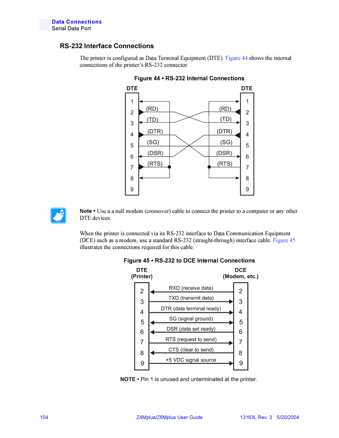
RS-232 Interface Connections
RS-232 Interconnections Using a DB-25 Cable
RS-422/RS-485 Interconnections
Parallel Cabling Requirements
Parallel Cable Pin Configuration
Parallel Data Port
Parallel Port Interconnections
108
Specifications
General Specifications
Z4Mplus and Z6Mplus General Specifications
Printing Specifications
Z4Mplus and Z6Mplus Printing Specifications
Media Specifications
Z4Mplus and Z6Mplus Media Specifications
Ribbon Specifications
Z4Mplus and Z6Mplus Ribbon Specifications
Printer Options
Z4Mplus and Z6Mplus Options
Zebra Programming Language ZPL II Features
UPC/EAN
Supported Bar Codes
Supported Bar Codes
Index
Index
Out of Memory message
120
13163L Rev 5/20/2004 Z4Mplus/Z6Mplus User Guide 121
122
Page
Customer Order # 13163LB Manufacturer 13163LB Rev ZIH Corp