Ground Resistance
Use this function to verify the protector ground resistance compared to a Central Office (C.O.) using the 965DSP and an active pair.
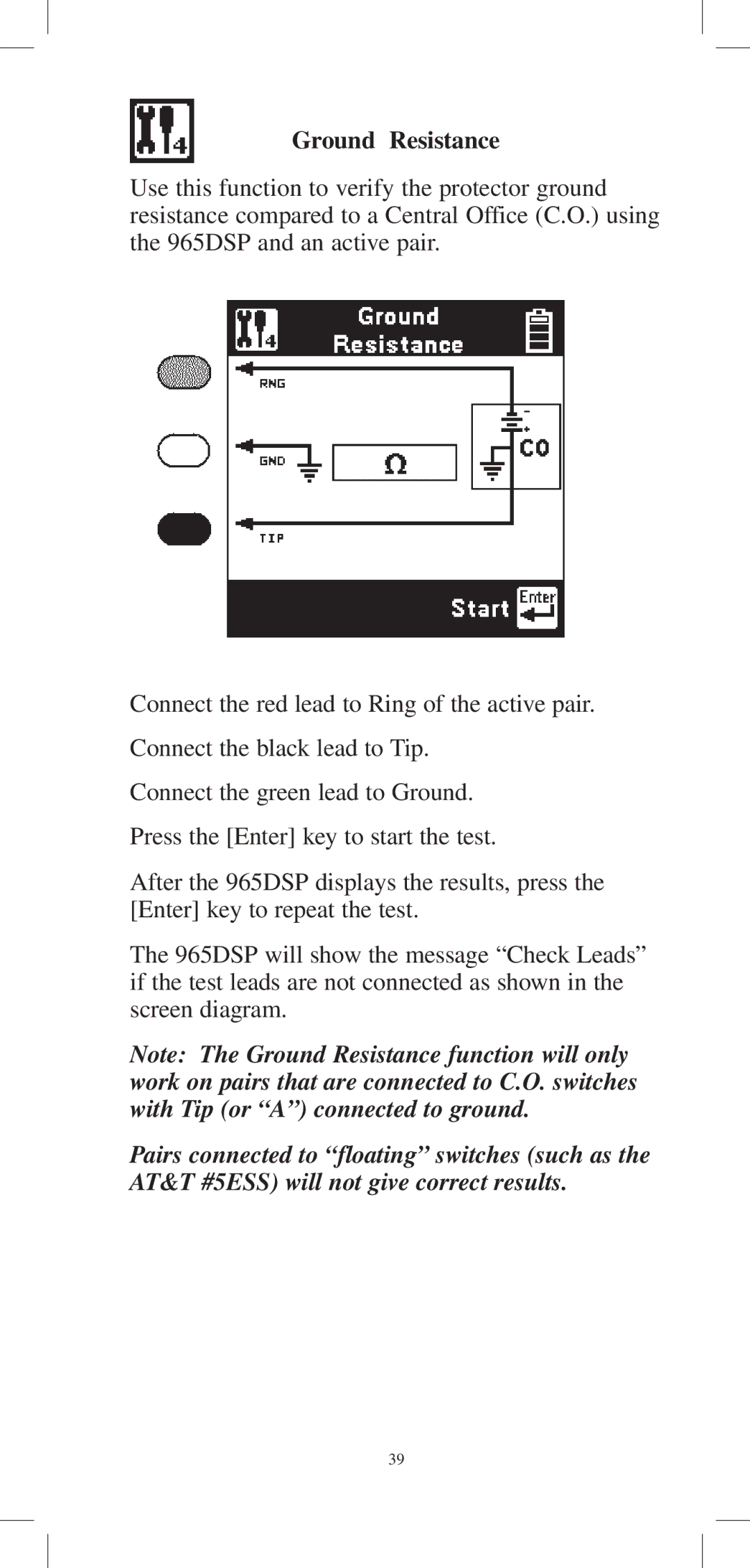
Connect the red lead to Ring of the active pair. Connect the black lead to Tip.
Connect the green lead to Ground. Press the [Enter] key to start the test.
After the 965DSP displays the results, press the [Enter] key to repeat the test.
The 965DSP will show the message “Check Leads” if the test leads are not connected as shown in the screen diagram.
Note: The Ground Resistance function will only work on pairs that are connected to C.O. switches with Tip (or “A”) connected to ground.
Pairs connected to “floating” switches (such as the AT&T #5ESS) will not give correct results.
39
