Manuals
/
A&D
/
TV and Video
/
Universal Remote
A&D
PD4000243
manual
Status Chart Mode map
Models:
PD4000243
1
21
144
144
Download
144 pages
46.14 Kb
18
19
20
21
22
23
24
25
Specification
Install
Error messages
Status Chart Mode map
Alarm 0utf-11 Output terminal
Calibration Error
Batch start delay timer
Symbols
Graphic Status Indicator
Connecting Loadcell Cable
Page 21
Image 21
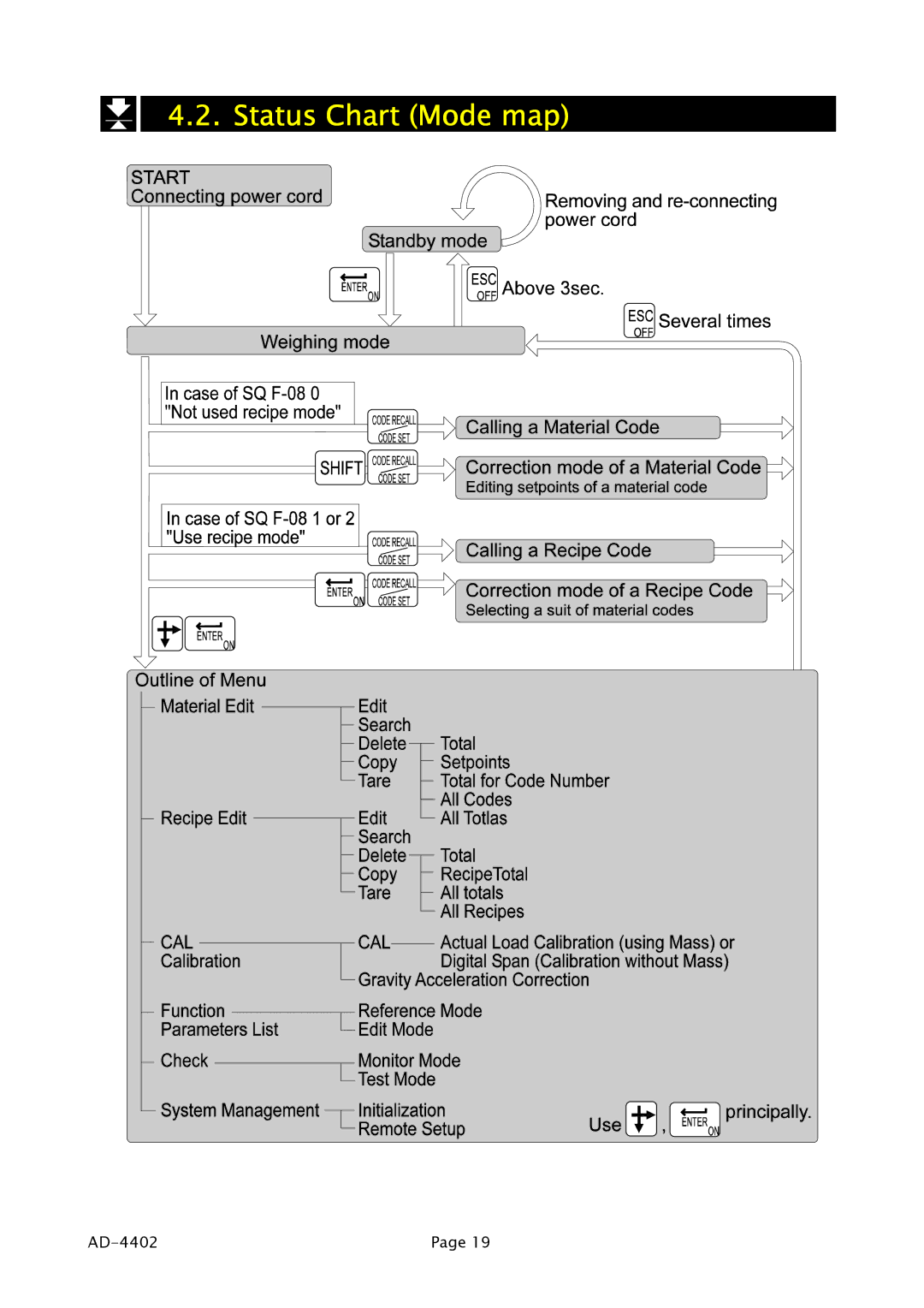
4.2. Status Chart (Mode map)
AD-4402
Page 19
Page 20
Page 22
Page 21
Image 21
Page 20
Page 22
Contents
Multi Function Weighing Indicator
Page
Contents
AD-4402
Remote Operation 102 Function List 103 10.1.1 Operation Keys
Compliance
Compliance with FCC rules
Compliance with European Directive
Outline and Features
Precaution
Keys
Front Panel
Alphanumeric keys
Symbols
NET
AC85V
Rear Panel
Mounting Indicator
Installation
Connecting Loadcell Cable
Loadcell Output Adjustment for Zero Calibration Zero Point
Adaptable Compression Terminal Parts
Verification Example
Verifying Loadcell Output and Input Sensitivity
Wiring Power Cord
Installing Options
Basic Operation
Standby Mode
Key Operation Examples
Cursor Operation
Way of Calling a Code
Way of Entering a Correction Mode
Case of a Material Code
Case of a Recipe Code
Way of Entering Menu
Status Chart Mode map
Common Calibration Items
Calibration
Items for the Actual Load Calibration
Items for Digital Span
ESC key
Actual Load Calibration using Mass
Digital Span Calibration without Mass
Gravity Acceleration Reference
Gravity Acceleration Correction
CERR1
Calibration Error
Hopper Scale with Material Code
Applications
Definition of Material Code
Recalling Material Code
Referring next Material Code
Editing Principle Parameters of Material Code
Edit Material Code
Editing Full Parameters of Material Code
Delete Material Code
Search Material Code
Example of Deleting Total Value
Copy Material Code
Tare of Material Code
Definition of Recipe Code Formal Function
Simple Hopper Scale with Recipe Code
Using a Recipe Code
Construction of Recipe Code
Recalling a Recipe Code
Editing Full Parameters of Recipe Code
Arranging Material Code in Recipe Code
Edit Name of Recipe Code
Search of Recipe Code
Copy of Recipe Code
System Design of Hopper Scale
Setup
Operation and I/O Design
Design Example
Contents of Batch Weighing Mode
Weighing Mode
Batch Weighing Mode
Loss-in-weight
Normal Batching
External Selection Normal batch weighing or Loss-in weight
Selection of Normal Batching or Loss-in-weight
Selection of Batch Weighing
Advise
Normal Batching of Sequential Weighing
Sequential Weighing Mode
Forecast Control Function
Concerning Parameters of the Function
Changing the timing of comparison
Drawing Normal Batching of Sequential Weighing
Loss-in Weight of Sequential Mode
Drawing Loss-in Weight of Sequential Weighing
Compensation Sequence
Drawing Compensation Sequential
Entrance Sequence
Drawing Entrance Sequence
Discharge Sequence
Drawing Discharge Sequence
Weighing a single material code during a recipe sequence
Plain Recipe Sequence
Drawing Plain Recipe Sequence
Automatic Selection of Supplying Mat
Case 1 Direct Gate Control
Case 2 Gate Control with Supplying Mat Selection
Nozzle Control Sequence vacuum cleaner
Mixture Sequence
Material
Pause and Emergency Stop
Safety Check Function
Restart Sequences from Pause
Automatic Free Fall Compensation
Real Time Free Fall Compensation
Customer Programmed Control Comparison Output
Arbitrary width can be set
Normal Batching of Comparison Function
Drawing Normal Batching of Comparison Function
Nn terminal number of the I/O
Loss-in Weight of Comparison Function
Batch start delay timer
Other Functions
Re-Zero Operation
Zero Tracking Function
Preset Tare Fixed Tare Function
Tare
Customizing Function Key Key Design
Customizing Sub Display
Row and Colum Address
Items to append to sub-display
Graphic Display
Accumulation Operation
Undoing Accumulation Operation
Clearing Deleting Accumulation Data
Kind of Alarm and Error
Error Message and Alarm
Dispaly can not be zeroed by zero compensation
Memory Backup
Graphic Status Indicator
Control I/O Function
Interface
Interface circuit
Input terminal
Function assigned to terminals
Timing Chart
Connection
Built-in RS-485 Interface
Way of Use and Note
Terminals
System Connections
Settings of Parameters
Communication Modes
Stream Mode
Weighing data
General Data Format
5. A&D Data Format
Address
Broadcast Address
Command List
Monitor Commands
Write Commands
Cetl
Control Commands
Ascii Code for AD-4402
Response Error Code
Communication Modes
Built-in Current Loop Output
Data Format
BCD Output of Option, OP-01
Connection
Terminals
AD-4402
When normal output 01f- 3 without 5 is used
Timing Chart
Terminal List
Relay Output of Option, OP-02
RS-422/485 Interface of Option, OP-03
RS-422 Connections
RS-485 4 Wire Connections
Settings of Parameters
RS-485 2 Wire Connections
RS-232C Interface of Option, OP-04
Parallel I/O of Option, OP-05
Analog Output of Option, OP-07
Monitor Mode
Maintenance
Basic Operation
Monitoring Control I/O Function
Monitoring A/D Converter
Monitoring Built-in Current Loop Output
Monitoring BCD Output of OP-01
Monitoring Relay Output of OP-02
Monitoring RS-232C Interface of OP-04
Monitoring RS-422/485 Interface of OP-03
Monitoring Parallel I/O of OP-05
Monitoring Analog Output of OP-07
Testing Control I/O Function
Test Mode
Testing Built-in RS-485 Interface
Testing Built-in Current Loop Output
Testing BCD Output of OP-01
Testing A/D Converter
Testing Relay Output of OP-02
Testing RS-422/485 Interface of OP-03
Testing RS-232C Interface of OP-04
Testing Parallel I/O of OP-05
Testing Analog Output of OP-07
Initializing Parameters
Kinds of intialization mode
To enter intialization
Prucedure
Remote Operation
Entering to the Remote Operation Mode
Function List
Operation Keys
Example of an item
Options
Outline of the Function List
Referring Parameters
Parameter Settings
Parameter List
Category address Function Function setting General Weighing
Category
5ub f
Key operation
Category address Function Function setting General Others
Clear all total data for material codes
Category
Category address Function Function setting Sequence Basic
Category address Function Function setting Sequence Control
Select a action at batch finish
Category address Function Function setting Sequence Timer
Second Digit
Category address Function Function setting Sequence Total
Category address Function Function setting Sequence Setpoint
Category address Function Function setting Sequence Safety
BCD
Terminal name Default choices Lt No
Discharge Open the dscharge gate
Alarm 0utf-11 Output terminal
Category address Function Function setting Serial RS-485
Category Range
OP-01 Option BCD Output
OP-02 Option Output Relay Output
Slot n slot number Category Range
Address symbol
Plural terminals and keys
OP-05 Option Parallel input / output
OP-07 Option Analog Output
General
Specifications
Analog to Digital Unit
Display
Connectors and interfaces
Weighing
Code data
Standard RS-485 interface
Standard I/O terminal
Current loop
BCD Output of Option
Accessories
Dimensions
Abbreviation
References
Ascii Code for AD-4402
Shift key
Index
113
Water-resistant panel
ページ
Tqv wxyww+yxr yus
Top
Page
Image
Contents