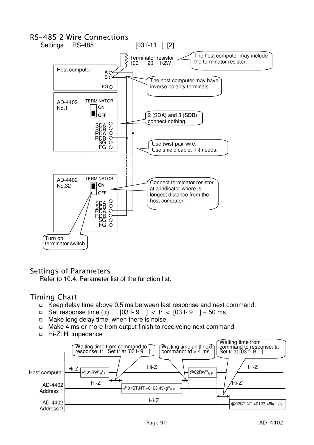
RS-485 2 Wire Connections
Settings | [03 |
Host computer | A |
| B |
| FG |
Terminator resistor | The host computer may include |
100 ~ 120Ω 1/2W | the terminator resistor. |
The host computer may have inverse polarity terminals.
TERMINATOR | |
| |
No.1 | ON |
| |
| OFF |
| SDA |
| SDB |
| RDA |
| RDB |
| SG |
| FG |
2 (SDA) and 3 (SDB) connect nothing.
Use
Use shield cable, if it needs.
No.32 |
|
|
| ON |
|
|
| ||
|
|
|
| OFF |
|
|
| SDA | |
|
|
| SDB | |
|
|
| RDA | |
|
|
| RDB | |
|
|
|
| SG |
|
|
|
| FG |
Turn on terminator switch
Connect terminator resistor at a indicator where is longest distance from the host computer.
Settings of Parameters
Refer to 10.4. Parameter list of the function list.
Timing Chart
Keep delay time above 0.5 ms between last response and next command. Set response time (tr). [03 f- 9] < tr < [03 f- 9] + 50 ms
Make long delay time, when there is noise.
Make 4 ms or more from output finish to receiveing next command
Waiting time from command to | Waiting time unitl next | Waiting time from |
command to response: tr. | ||
response: tr. Set tr at [03 f- 9]. | command: td > 4 ms | Set tr at [03 f- 9]. |
Host computer
Address 1
Address 2
@01RWCRLF
@01ST,NT,+0123.45kgCRLF
@02RWCRLF
@02ST,NT,+0123.45kgCRLF
Page 90 |
|
