Service
Theory of Operation
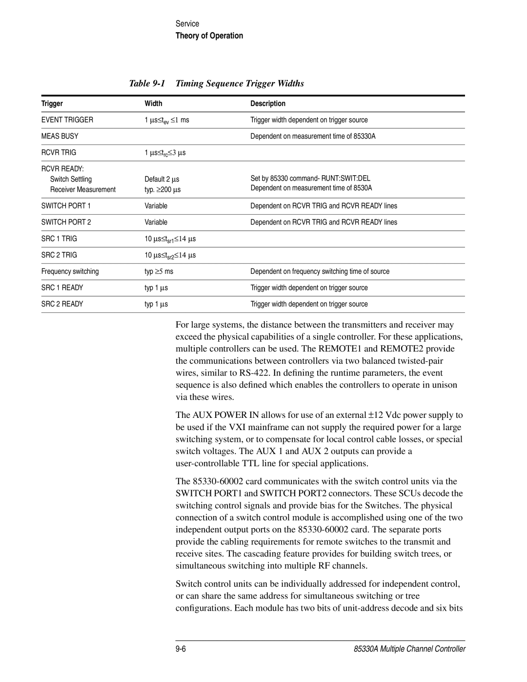
Table 9-1 Timing Sequence Trigger Widths
Trigger | Width | Description | ||
|
|
| ||
EVENT TRIGGER | 1 ∝s≤ tev ≤1 ms | Trigger width dependent on trigger source | ||
|
|
|
|
|
MEAS BUSY |
|
|
| Dependent on measurement time of 85330A |
|
|
| ||
RCVR TRIG | 1 ∝s≤ trc≤3 ∝ s |
| ||
|
|
|
|
|
RCVR READY: |
|
|
|
|
Switch Settling | Default 2 ∝s | Set by 85330 command- RUNT:SWIT:DEL | ||
Receiver Measurement | typ. | ≥ | ∝ | Dependent on measurement time of 8530A |
| 200 s |
| ||
SWITCH PORT 1 | Variable | Dependent on RCVR TRIG and RCVR READY lines | ||
|
|
| ||
SWITCH PORT 2 | Variable | Dependent on RCVR TRIG and RCVR READY lines | ||
|
|
| ||
SRC 1 TRIG | 10 ∝s≤ tsr1≤14 ∝ s |
| ||
|
|
| ||
SRC 2 TRIG | 10 ∝s≤ tsr2≤14 ∝ s |
| ||
|
|
|
| |
Frequency switching | typ ≥5 | ms | Dependent on frequency switching time of source | |
|
|
| ||
SRC 1 READY | typ 1 ∝s | Trigger width dependent on trigger source | ||
|
|
| ||
SRC 2 READY | typ 1 ∝s | Trigger width dependent on trigger source | ||
|
|
|
|
|
For large systems, the distance between the transmitters and receiver may exceed the physical capabilities of a single controller. For these applications, multiple controllers can be used. The REMOTE1 and REMOTE2 provide the communications between controllers via two balanced
The AUX POWER IN allows for use of an external ±12 Vdc power supply to be used if the VXI mainframe can not supply the required power for a large switching system, or to compensate for local control cable losses, or special switch voltages. The AUX 1 and AUX 2 outputs can provide a
The
Switch control units can be individually addressed for independent control, or can share the same address for simultaneous switching or tree configurations. Each module has two bits of
85330A Multiple Channel Controller |