Performance Verification
Verifying the Multiple Channel Controller
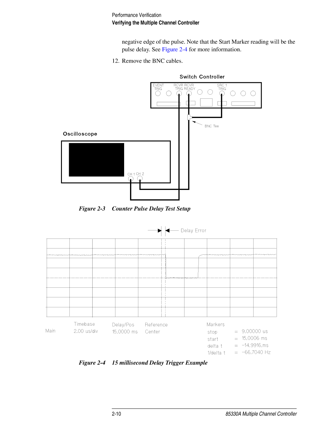
negative edge of the pulse. Note that the Start Marker reading will be the pulse delay. See Figure
12. Remove the BNC cables.
Figure 2-3 Counter Pulse Delay Test Setup
Figure 2-4 15 millisecond Delay Trigger Example
85330A Multiple Channel Controller |
